Before the start of typesetting design, Xiaobian wants to interpret several concepts and viewpoints in order to facilitate the following typesetting design: first, scaffold design and construction are not 100% qualified, and some things can be compromised on the premise of ensuring safety and control
. 
Second: the vertical distance of the pole is not fixed at 1.5m, but can be greater or less than 1.5m, as long as the site is consistent with the scheme
. 
Article 6.1.1 of jgj130-2011 technical code for safety of fastener type scaffold in building construction: the word used in the code is “can”
. 
Obviously, it can be used or not! Third, the cross of cross bracing on the vertical pole is not only the standard requirement, but also the aesthetic demand
. 
Friendly tips: if the readers agree with the above three points, they can continue to look down
. 
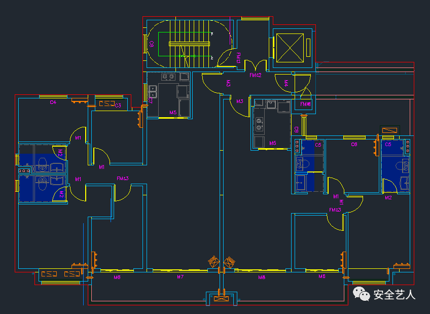
If they don’t agree, they can stop The first step of the design is to draw the outline of the building (red lines)
. 
The second step is to leave the distance between the outer frame and the wall according to the construction requirements
. 
In this case, the distance from the wall is 300 mm (the contour line is offset by 300 mm, and the white line in the figure below)
. 
The third step is to offset the transverse distance of the outer frame again
. 
In this case, the transverse distance of the vertical pole is 800 mm
. 
At this point, the plane outline of the outer frame has come out
. 
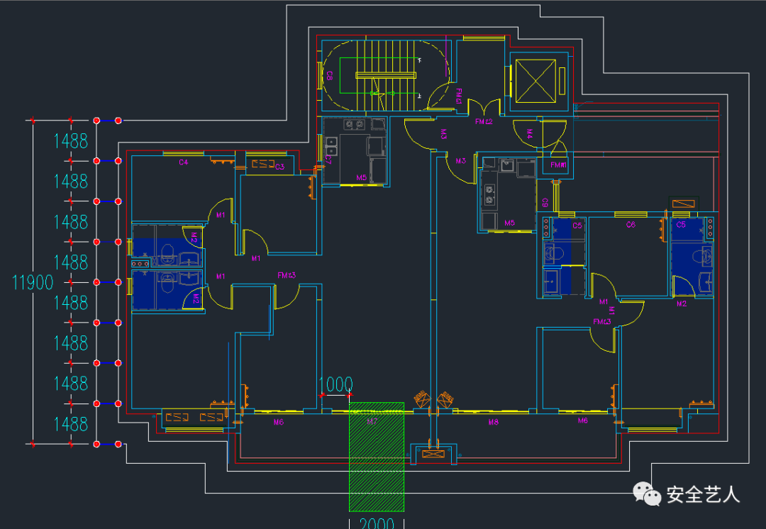
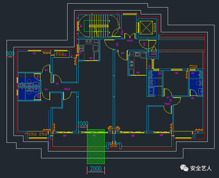
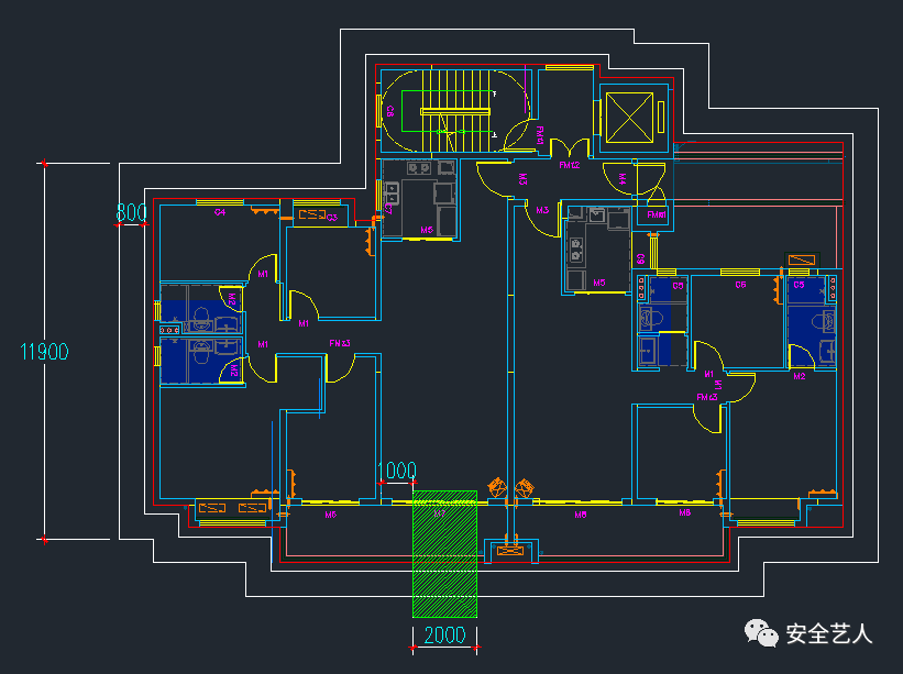
The fourth step is to determine the width and specific location of the unloading platform and the construction elevator
. 
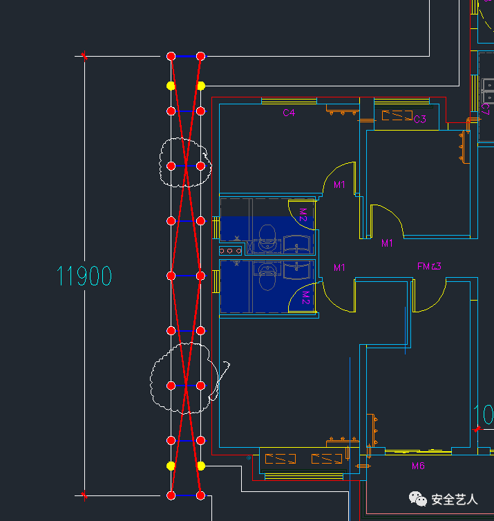
Here, only the distance of the unloading platform is explained: the width of the unloading platform is 2000mm, and the location is as follows: the fifth step is to take the West gable as an example to make the vertical layout: the layout principle is to divide even number of spans equally! Measure the width of the outer frame of the West gable, as shown in the following figure: 1190011900 / 1500 = 7.9
. 
Take the largest even number from 7.9, that is, divide it into 8 spans
. 
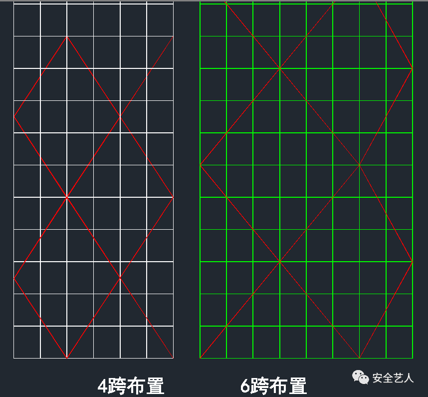
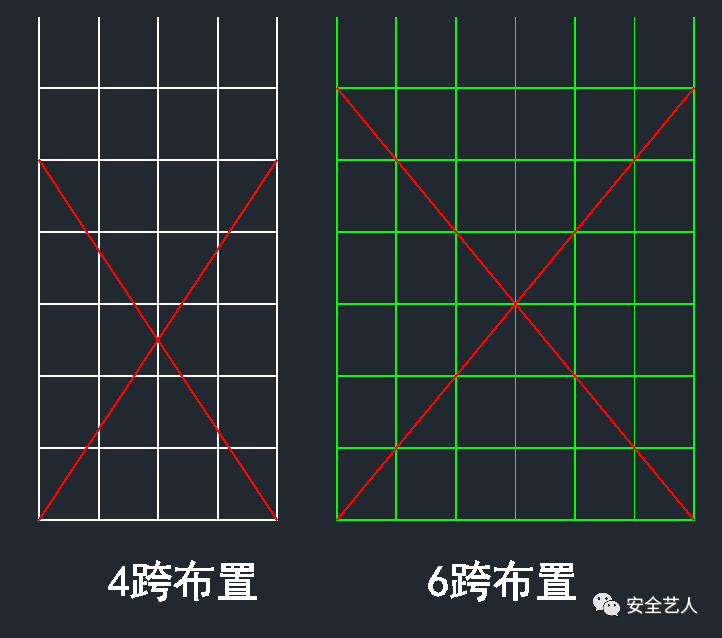
Then the longitudinal distance is 11900 / 8 = 1487.5mm, as shown in the following figure: why even number? Is to cross the center of the diagonal bracing on the vertical pole, as shown in the figure below: the following is to solve is, is the diagonal bracing 4 longitudinal distance or 6 longitudinal distance? As less than the whole cross bracing, the effects of the two schemes are as follows
. 
It is obvious that if the cross bracing is arranged according to 4 spans, an elevation is either complete or supplemented with half cross bracing, but the angle of the cross bracing is the same; while if the cross bracing is arranged according to 6 spans, when an elevation cannot form a complete cross bracing, the cross bracing of an elevation is composed of N + 0.6N, and the angle is the same If n + 0.3n, no matter which layout, the remaining incomplete diagonal angle is inconsistent
. 
So, we choose 4-span cross bridging
. 
In this way, the layout of the Western gable wall is as follows
.
Of course, in order to simplify the drawing process, we use the method of “horizontal marking of cross bracing” initiated by Xiaobian: it is very clear that the cross bracing is crossed on the vertical pole
.
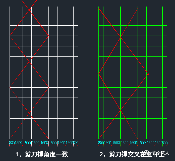
In order to more thoroughly express the advantages of “cross bracing flat marking”, the following uses the traditional typesetting method for comparison
.
As shown in the figure below, according to the traditional typesetting method, stick to the vertical distance of 1500, without considering the equal spacing typesetting, the cross point of cross bracing and cross bracing will not be on the upright pole
.
Of course, if the cross is forced on the vertical pole, the angle of the cross bracing is not consistent, as shown in the following figure: obviously, the two methods are either out of line or ugly
.
Then, the sixth step is to arrange the layout on both sides of the elevator or unloading platform according to the above principles
.
The vertical poles on both sides of the material platform shall be reserved 150 ~ 200 mm according to the lifting requirements of the material platform
.
There is no vertical pole in the range of material table
.
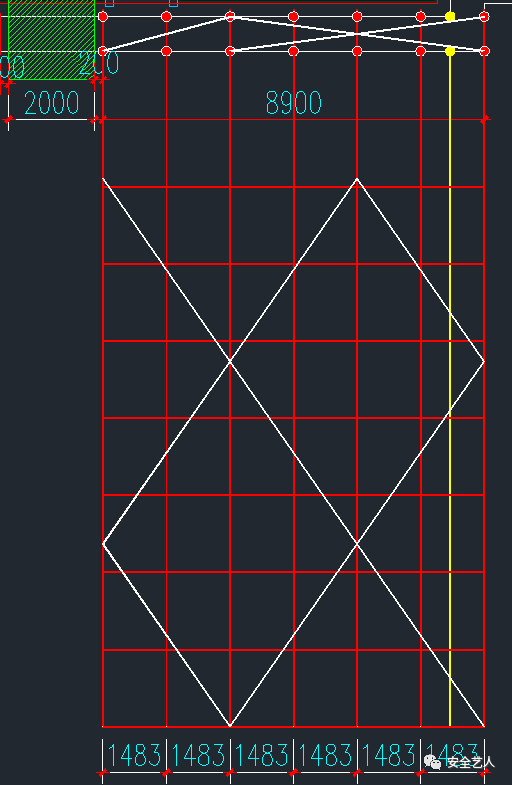
In the seventh step, according to the above principles, the vertical bar layout is: 8900 / 1500 = 5.9, take 6, then the longitudinal distance is 8900 / 6 = 1483mm
.
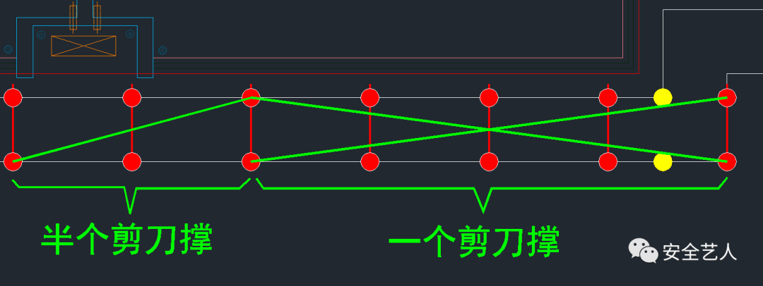
The corresponding elevation effect diagram is as follows: in order to more clearly discuss the “cross bracing Horizontal method marking”, here we use the detailed drawing to explain, as shown in the following figure, one complete cross bracing, horizontal method marking, cross bracing travel, half cross bracing, in Horizontal method marking, similar to the “zigzag brace” drawing
.
The eighth step is to improve the layout of vertical poles at other positions according to this step
.
The ninth step is to arrange cantilever I-beams according to the position of vertical poles
.
In principle, there are I-beams under each vertical pole
.
When I-beams cannot be set under the vertical pole due to structural reasons, coupling beams are set
.
Because it’s too simple, I won’t repeat it here..
.