Scaffold erection specification is a working platform to ensure the smooth progress of the construction process
.
As an almost essential part of the construction project, its erection operation is crucial to the whole project
.
Quality standard of scaffold structure accessories 1
.
Steel pipe 1
.
Steel pipe (1) steel pipe adopts No
.
3 welded steel pipe with outer diameter of 48mm and wall thickness of 3.5mm, and shall have product quality certificate and inspection report
.
Those seriously corroded must be replaced and shall not be used for erecting frame body
.
(2) The steel pipe surface shall be straight and smooth without cracks, scabs, delamination, dislocation, hard bending, burr, indentation and deep scratch
.
The steel pipe with serious corrosion, bending, flattening, damage and crack shall not be used
.
(3) The steel pipe shall be coated with antirust paint
.
The vertical and horizontal poles are painted with yellow antirust paint, and the cross braces and handrails are painted with red and white paint
.
The maximum mass of each steel pipe shall not be greater than 25kg
.
It is forbidden to drill holes on steel pipes
.
(4) The length of steel pipe for vertical and longitudinal horizontal bar (large cross bar) is 3-6M, the length of steel pipe for transverse horizontal bar (small cross bar) is 1.1-1.3m, and the length of steel pipe for transverse diagonal brace is 3-4m
.
2
.
Fasteners (1) new fasteners shall have production license, product quality certificate and inspection report
.
The quality of old fasteners should be checked before use
.
The ones with cracks and deformation are strictly forbidden to use
.
The bolts with sliding wires must be replaced
.
Both new and old fasteners should be treated with anti rust treatment
.
Repair and replace the seriously rusted and damaged fasteners in time
.
The oil on the bolt is guaranteed and easy to use
.
(2) The joint surface between the fastener and the steel pipe shall be in good contact
.
When the fastener clamps the steel pipe, the minimum distance at the opening shall be less than 5mm
.
The fastener used shall not be damaged when the bolt tightening force reaches 65N
.
M
.
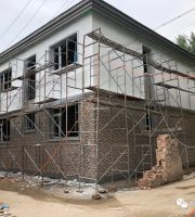
Construction procedures, methods and requirements of scaffold erection (1) scaffold body form the project adopts 16 ᦇ I-steel cantilever single vertical pole double row external scaffold
.
The step distance of cantilever scaffold is 1.8m, the vertical distance of upright pole is 1.5m, and the distance between inner and outer upright poles is 0.85m; the small cross bar is set under the large cross bar, the distance between outer large cross bar is 0.9m, the distance between inner large cross bar is 1.8m, and a horizontal cross bar is added in the middle of the small cross bar
.
(2) scaffold erection construction procedure 1
.
Scaffold cantilever beam placement (1) cantilever beam rings are embedded according to the scheme requirements, with accurate position and appropriate size
.
(2) the setting out and positioning shall be carried out according to the requirements of the longitudinal distance and transverse distance of the scaffold
.
(3) place the I-beams one by one, place the I-beams well, pull the through line for positioning, and then weld and anchor with reinforcement
.
(4) when the cantilever beam is lifted and transported, it should be lifted and placed gently to reduce the impact on the structural deflection safety of concrete
.
2
.
The erection sequence of the scaffold is from one end of the corner of the building to erect the vertical pole one by one → place the longitudinal sweeping pole (the big cross bar close to the cantilever beam), and then fasten it with the vertical pole → install the transverse sweeping pole (the small cross bar close to the cantilever beam), and fasten it with the vertical pole → after erecting 3-4 vertical poles, install the first step big cross bar (pay attention to fasten it with each vertical pole) → install the first step small cross bar (with the big cross bar) Fastening) → installation of wall connecting parts (or temporary throw bracing) → installation of the second step large cross bar → installation of the second step small cross bar → third and fourth steps large cross bar and small cross bar → installation of wall connecting rod at corresponding position → connection of each vertical bar (6m in length) → addition of cross bracing and transverse diagonal bracing → erection of waist handrail and toe board → full laying of bottom scaffold board → hanging of safety net (including horizontal net and vertical net)
.
3
.
Precautions for scaffold erection (1) before fixing the bottom of the vertical pole, the line should be suspended to ensure that the vertical pole is vertical
.
(2) after correcting the verticality of the vertical pole and the level of the large cross bar to make them meet the requirements, tighten the fastener bolts to form the initial section of the frame body, and extend the erection forward in sequence according to the above erection sequence until the first step of frame crossing is completed
.
After each scaffold is erected, correct the step distance, longitudinal distance, transverse distance and verticality of the vertical pole to ensure that they meet the requirements, then set up the wall connecting pieces and set up the last step
.
(3) the scaffold must be erected in accordance with the construction progress, and the height of one erection shall not exceed two steps above the adjacent wall connecting parts
.
(3) scaffold erection methods and requirements 1
.
The longitudinal sweeping pole is required to be fixed on the vertical pole not more than 100 mm away from the base with right angle fasteners
.
The horizontal sweeping pole is fixed on the vertical pole close to the bottom of the longitudinal sweeping pole by right angle fasteners
.
2
.
Requirements for erection of vertical pole (1) steel pipe used for vertical pole must be coated with antirust paint, and bending steel pipe is not allowed
.
The vertical pole should be at least 1.5-1.8m higher than the working face
.
(2) detailed method of vertical pole joint: the vertical pole must be lengthened by butt joint, the butt fasteners on the vertical pole shall be staggered, the joints of two adjacent vertical poles shall not be set in synchronization, the staggering distance between the height direction of two adjacent vertical pole joints shall not be less than 500mm, and the distance between the center of each joint and the main node shall not be greater than 1 / 3 of the step distance
.
3
.
Requirements for erection of large cross bar (1) the large cross bar shall be set inside the vertical bar and fixed on the vertical bar with right angle fastener, and its length shall not be less than 3 spans
.
In the same step of the scaffold, the big cross bar should be surrounded and fixed with the inner and outer corner vertical bar
.
(2) detailed method of large cross bar joint: large cross bar shall adopt butt joint, butt joint shall be staggered, and shall not be set in the same span at the same time, the horizontal distance between adjacent joints shall not be less than 500mm, and the distance between joint and adjacent vertical bar shall not be greater than 1 / 3 of vertical bar spacing
.
4
.
The erection of small cross bar requires that a small cross bar must be set at the main node (the intersection of vertical bar and large cross bar), and the right angle fastener shall be used to fasten on the upper part of the large cross bar, the extension length of the outer end shall not be less than 100 mm, the extension length of the end against the wall shall not be less than 200 mm, and the distance to the wall decorative surface shall not be more than 100 mm
.
The distance between the axis of the pole and the main node should not be more than 150 mm
.
5
.
Fastener installation requirements (1) the fastener specification must be the same as the outer diameter of the steel pipe
.
(2) the tightening torque of fasteners should be 40-50n
.
M, and the maximum should not exceed 60N
.
M
.
it must be ensured that each fastener meets the requirements
.
(3) the distance between the center points of right angle fastener and rotary fastener used to fix small cross bar, large cross bar, cross brace, transverse diagonal brace, etc
.
at the main node shall not be greater than 150 mm
.
(4) the opening of butt fastener shall face the inner side of the shelf, and the opening of right angle fastener shall not face down
.
(5) the length of each rod end extending out of the edge of fastener cover plate shall not be less than 100 mm
.
6
.
Requirements for the connection between the frame and the building structure (1) structural form: the connection point is fixed on the embedded steel pipe with steel pipe fastener, and the cantilever horizontal steel beam is connected with the building with steel wire rope
.
The tie rod must be set on the vertical rod, and the inner and outer vertical rods shall be pulled at the same time
.
The tie bars are arranged horizontally
.
When they cannot be arranged horizontally, the end connected with the scaffold should be connected downward and not upward
.
(2) layout requirements: the wall connecting parts are arranged in two steps and three spans, with vertical spacing of 3.6m and horizontal spacing of 4.5m, and connected by double fasteners
.
The scaffold must be firmly tied with the main body of the building
.
The distance from the main node should not be more than 300 mm
.
It must be set from the first big cross bar at the bottom, with diamond layout
.
(3) the fastener used in the pull-out joint must meet the requirements, and the fastener shall not be loose or the embedded steel pipe shall not be bent
.
7
.
Setting up method of cross bracing (1) continuous setting of cross bracing in the whole length and height direction outside the scaffold
.
Each cross brace is connected with 5 vertical poles
.
The cross bracing should be erected simultaneously with the vertical bar, large cross bar and small cross bar.
.