3
. 
4
.
Before the water supply system is put into use, the water test must be carried out, the valve and water nozzle must be opened, the water discharge condition must be observed and recorded
.
After all bonding, the pipeline shall be straight, the slope shall be uniform, and the position of each reserved opening shall be accurate
.
Main pipe installation: 1
.
All valves must pass the pressure test before they can be used
.
The outer diameter of DN 100 is d = 114 mm
.
Be familiar with the drawings carefully, refer to the relevant professional equipment drawings and architectural decoration drawings, and check whether the coordinates and elevations of various pipelines intersect
.
2
.
Inspection method: observe the metal and composite pipe water supply pipeline system under the test pressure for 10 min, the pressure drop shall not be greater than 0.02 MPa, and then drop to the working pressure for inspection, and it shall be qualified if there is no leakage
.
This is the middle section expansion
.
The fabrication of supports and hangers is concentrated in the processing field to facilitate the control of the fabrication quality of supports
.
Pipe thread connection: lead oil hemp wire and polytetrafluoroethylene raw material belt are used as connecting filler
.
prefabrication: according to the requirements of the construction drawings and the actual situation, measure the size according to the reserved opening position, draw the processing sketch, measure the pipe size according to the sketch, and cut the pipe
.
When machining, it is required to use a shearing machine or a grinding wheel cutting machine
.
Prefabrication: according to the design drawings, draw the construction sketches of pipeline shunting, pipe diameter, diameter change, reserved pipe orifice, valve position, etc., mark the structural position of actual installation, measure the accurate size of actual installation according to the marked section, record it on the construction sketch, then prefabricate according to the size measured in the sketch, and group and number according to the pipe section
.
Draw a straight line with the length of D = 114mm, make a 1’1 vertical line with the length of B / 2, and the vertical foot is 1
.
All kinds of fillers can only be used once in the thread
.
Connect 1’7 ‘, extend the vertical line to intersect 2’3’4’5’6’, pass 1 ‘, 2’, 3 ‘, 4’, 5 ‘, 6’, 7 ‘for horizontal ray
.
After the trial insertion is qualified, wipe the moisture and dust of the socket to be bonded with cotton cloth
.
The adhesion of the two segments must also be carried out in sequence according to the bonding process
.
As shown in the following figure: 1
.
Make the vertical line of E-F according to the equal points, and cross the horizontal line of 1’2’3’4’5’6’7 ‘at points 1’, 2 ‘, 3’, 4 ‘, 5’, 6 ‘, 7’
.
Derusting and painting shall be carried out after the supports and hangers are manufactured, and the top coat shall be painted as required
.
Draw a semicircle with the diameter of 1-7, and then divide the semicircle into 6 equal parts
.
Then cut it along the line, stick it on the pipe, and then draw lines and cut it
.
When inserting the adhesive, rotate the socket slightly to make the adhesive evenly distributed
.
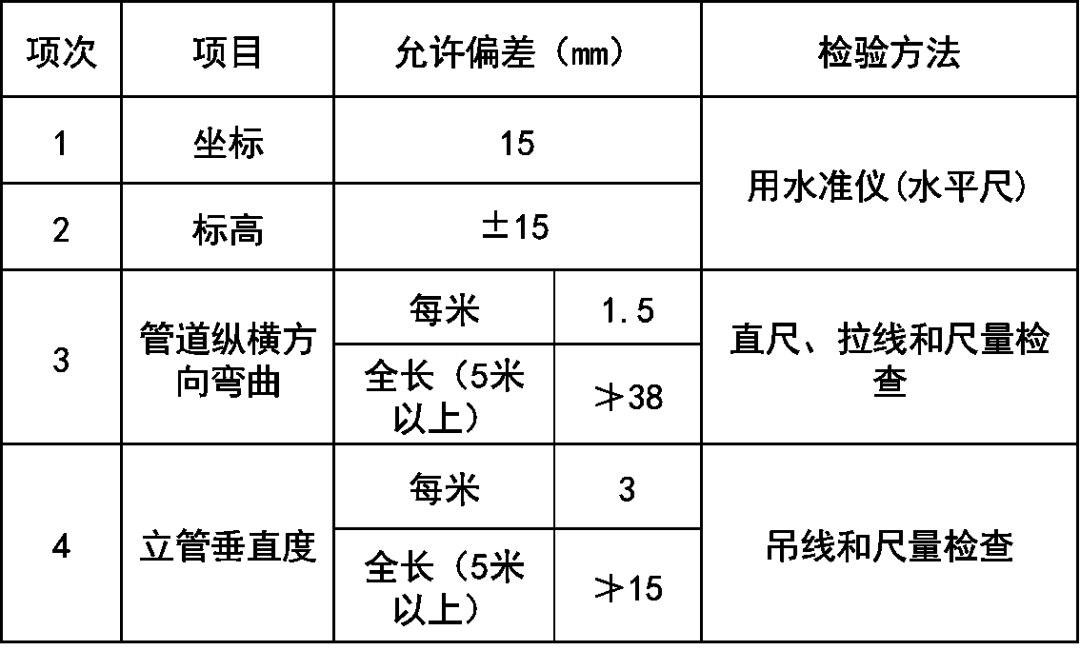
Allowable deviation of pipeline and valve installation: (7) pipeline pressure test – comprehensive hydraulic test shall be conducted after pipeline system installation
.
Process flow: Installation Preparation → prefabrication processing → support installation → main pipe installation → riser installation → branch pipe installation → sealing and plugging → closed water test
.
Cut 1’1, 2’2, 3’3, 4’4, 5’5, 6’6, 7’7 vertical EF and points 1 ‘, 2’, 3 ‘, 4’, 5 ‘, 6’, 7 ‘, respectively, and then connect 1234567 with smooth curve
.
Pipe supports and hangers: pipe supports and hangers are made of angle steel on site
.
6
.
The buried underground pipeline shall be backfilled with fine sand to 100 mm above the pipe surface, covered with sieved soil, and the pipeline shall not be damaged during compaction.
.
Use smooth curves to connect 1 ”, 2 ”, 3 ”, 4 ”, 5 ”, 6 ”, 7 ”, 6 ”, 5 ”, 4 ”, 3 ”, 2 ”, 1 ”, respectively
.
Temporary plugs are added to the branch pipes
.
The pressure test of the pipeline system shall be carried out in different areas, and the test pressure of the water supply pipeline system shall be 1.5 times of the working pressure, but not less than 0.6MPa
.
The total length of broken and missing thread after processing shall not exceed 10% of the full thread length
.
The pipe is fixed on the support and hanger with U-shaped pipe clamp or special elevator
.
When the construction conditions are met, the prefabricated pipe section shall be transported to the installation site for installation according to the number
.
Attention should be paid to the direction of opening when multi opening bonding
.
After the adhesive is firmly bonded, wipe off the overflow adhesive immediately
.
The bracket and hanger shall be made according to the design coordinate, elevation, aspect and gradient
.
This curve is the expanded view of the end section of the welded elbow
.
5
.
Main pipe installation: first of all, according to the coordinates and elevation required by the construction drawings, groove holes or embedded casing are reserved
.
Installation Preparation: 1
.
According to the length of the pipe, the temporary fixing card shall be properly added
.
The pipe is fixed on the support and hanger with U-shaped pipe clamp or special elevator
.
Installation preparation → prefabrication → main pipe installation → branch pipe and pipeline valve installation → branch pipe installation → pipeline imitation and insulation → pipeline flushing and pressure test
.
Screw tail shall be left after tightening; after pipe connection, the packing squeezed outside the bolt shall be removed
.
Operation process: A
.
The support and hanger shall be connected by welding, and the welding requirements shall meet the welding quality standards
.
Extend the 1-7 horizontal line, and take E-F = pipe perimeter (π d), where D is the outer diameter of the pipe, and then divide E-F into 12 equal parts
.
The packing shall not be squeezed into the pipeline to avoid blocking the pipeline
.
The fracture surface should be even, and the internal and external flying thorns of the fracture surface should be removed with a milling cutter or scraper, and the external edge should be milled to a 15 ° angle
.
Drainage pipe installation: 1
.
After leveling and alignment, the branch pipe clamp shall be inserted
.
The expansion bolt holes of the support shall be drilled with a drilling machine, and the holes shall not be cut with oxygen
.
If there is a problem on the drawing, it should be studied and solved with the relevant design personnel in time, and the change record should be well kept
.
After the installation, the plumber is used for straight alignment, and the floor hole is blocked in cooperation with the civil engineering
.
b
.
The maximum spacing requirements of pipe supports and hangers are shown in the table below: the supports and hangers are connected by welding method, and the welding requirements shall meet the welding quality standards
.
Apply the adhesive with a brush, first coat the socket, then coat the socket, and then insert it vertically with force
.
The marks during straightening shall be well aligned and 2 to 3 threads shall be missed
.
2
.
So r = 171 mm
.
The flushing shall be carried out continuously with tap water to ensure sufficient flow
.
Make the vertical line of 1-7 intersecting with points 2, 3, 4, 5 and 6
.
Anti rust paint shall be applied to the damaged part of the leakage thread and galvanized layer
.
According to the above formula: according to the height of the back (A / 2) and the height of the abdomen (B / 2), the expanded view of the end segment can be drawn
.
2
.
Key points of connection: during thread connection, the packing shall be laid on the outside of the thread at the pipe end, 2-3 buckles shall be screwed by hand, and then the pipe clamp shall be used to tighten it at one time, and it shall not be reversed
.
The buried pipe and the main pipe in the ceiling shall be subject to closed water test, and can be concealed only after passing the test
.
Go through the acceptance procedures after washing and cleaning
.
2
.
3
.
When buried underground, the trench shall be excavated and compacted according to the design coordinates, elevation, aspect and gradient
.
The installation direction of riser valve shall be convenient for operation and repair
.
7
.
(8) The pipeline can be flushed after the completion of pressure test
.
It is required that the deviation per meter and the total length of the pipeline should be less than or equal to 1 mm and 10 mm respectively
.
The temporary fixing card shall be removed and the temporary plug shall be installed
.
The drawings should be combined with the actual situation on site
.
If there is any intersection, it should be based on the principle of pressure giving way to non pressure and small pipe giving way to large pipe
.
If the thread is disassembled and re tightened, new fillers should be replaced
.
The prefabricated risers shall be arranged layer by layer according to the number and installed in sequence
.
4
.
3
.
[example] try to use welded steel pipe to make an elbow with DN of 100 mm, bending angle of 90 ° and R = 1.5D
.
Before bonding, the socket should be inserted in the test, not all of them should be inserted, generally 3 / 4 of the depth of the socket
.
The adhesive can be firmly bonded in about 30 seconds to one minute
.
If the branch pipe is equipped with a water meter, install the connecting pipe first, and remove the connecting pipe before handing over after pressure test
.
The height and position of the cold and hot water reserved opening of different sanitary appliances shall be checked and verified
.
Make a 7’7 vertical line with length of a / 2, and the vertical foot is 7
.
The hemp thread shall be removed and the height and direction of reserved opening shall be checked
.
The prefabricated branch pipes shall be installed from the vertical pipe opening section by section in turn
.
The pipe clamp shall be installed from top to bottom in each layer
.
Derusting and painting shall be carried out after the supports and hangers are manufactured, and the top coat shall be painted as required
.
