Source: talk about the three-dimensional diagram of raft reinforcement construction (in line with 16g101), you will learn after reading it! 1
. 
Scope of application: it is applicable to the foundation raft reinforcement construction of building structure engineering
. 
2
.
Process characteristics: clear raft foundation reinforcement construction process; guide raft and foundation beam reinforcement layout; sketch raft horse stool reinforcement layout and form
.
3
.
Construction preparation 3.1 technical preparation (1) be familiar with the drawings and complete the cutting of reinforcement
.
(2) Draw the reinforcement position line on the cushion
.
(3) Do a good job in technical disclosure
.
3.2 material requirements (1) all types and specifications of steel bars in the project must meet the design requirements
.
The factory certificate of steel bars shall be checked and retested according to the regulations
.
The steel bars can only be used after passing the inspection
.
The steel bar is free of corrosion and pollution, and the formed steel bar is qualified by field inspection
.
(2) The semi-finished products of reinforcement meet the requirements of design specifications
.
(3) The galvanized steel wire for steel bar binding can be 20 ~ 22 steel wire, of which 22 steel wire is only used for binding steel bar with diameter less than 12mm
.
3.3 main machines and tools: steel cutting machine, bending machine, straightening machine, steel hook, stone pen, ink bucket, ruler, etc
.
3.4 working conditions (1) the construction of foundation cushion or waterproof protective layer is completed and meets the design requirements
.
The reinforcement position lines of the wall, column, foundation beam, sump and raft on the cushion or waterproof protective layer have been snapped
.
(2) The reinforcement shall be stacked according to the designated position in the site layout plan
.
If there is rust on the outer surface of the reinforcement, it shall be cleaned before binding
.
The seriously corroded reinforcement shall not be used
.
(3) The place of binding reinforcement has been cleaned up
.
4
.
Process flow: 4.1 flat raft (concealed beam) foundation raft reinforcement construction 4.1.1 flat raft (concealed beam) foundation reinforcement model diagram, as shown in Figure 9-1
.
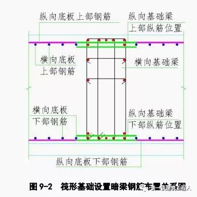
4.1.2 reinforcement construction process: completion of cushion layer or waterproof protective layer construction → setting out of wall, column, (concealed beam), pile cap and sump → drawing reinforcement location line → binding reinforcement of sump and pile cap → binding reinforcement of raft bottom (additional reinforcement and radial reinforcement) → placing cushion block → (binding reinforcement of concealed beam) → installation of horse stool reinforcement → top reinforcement of raft → column and wall joint reinforcement → acceptance Note for the next procedure: when there is a concealed beam, the position relationship between the beam reinforcement and the raft reinforcement shall be constructed as shown in Figure 9-2
.
4.2 beam slab raft (high slab and middle slab) foundation 4.2.1 beam slab raft (high slab and middle slab) foundation reinforcement model drawing, as shown in Figure 9-3 and figure 9-4
.
4.2.2 reinforcement construction process: completion of cushion layer or waterproof protective layer construction → setting out of wall, column, foundation beam, pile cap and sump → drawing reinforcement location line → binding reinforcement of sump, pile cap and foundation beam → binding reinforcement at raft bottom (additional reinforcement and radial reinforcement) → placing cushion block → installation of horse stool reinforcement → raft top reinforcement → column and wall joint reinforcement → acceptance for next process Meaning: during the construction of the high position raft, the position relationship between the beam reinforcement and the upper reinforcement of the raft and between the beam and the beam reinforcement shall be bound as shown in Fig
.
9-5
.
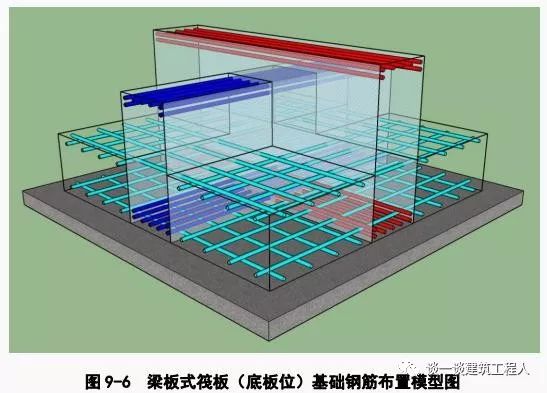
4.3 beam slab raft (bottom slab) foundation 4.3.1 beam slab raft (bottom slab) foundation reinforcement model, as shown in Figure 9-6
.
4.3.2 reinforcement construction process: completion of cushion layer or waterproof protective layer construction → setting out of wall, column, foundation beam, pile cap and sump → drawing reinforcement location line → binding reinforcement of sump and pile cap → binding reinforcement at raft bottom (additional reinforcement and radial reinforcement) → placing cushion block → binding reinforcement at foundation beam → installation of horse stool reinforcement → binding reinforcement at raft top → column and wall joint reinforcement → acceptance Next step
.
Attention: during the construction of high position raft, the position relationship between beam reinforcement and lower layer reinforcement of raft and between beam reinforcement
.
Bind as shown in Figure 9-7, figure 9-8, figure 9-9 and figure 9-10
.
4.4 reinforcement of elevator pit and sump 4.4.1 reinforcement model of elevator pit and sump, as shown in Figure 9-11
.
4.4.2 construction process of reinforcement: completion of cushion or waterproof protective layer construction → setting out of sump → drawing of reinforcement position line → binding of reinforcement in sump (two-way) → binding of reinforcement at the bottom of raft (additional reinforcement and radial reinforcement) → placement of cushion block → installation of horse stool reinforcement → binding of reinforcement at the top of raft → acceptance for next work, as shown in Figure 9-12
.
5
.
5.1 reinforcement setting out
.
Before the binding of raft reinforcement, the snapping line of foundation axis is completed, the foundation setting out work must be accepted, and the position line of raft reinforcement has been snapped, especially in the position line of column joint reinforcement, wall side line, foundation beam, sump, etc., the red paint shall be used to draw the mark of not less than 50 mm wide and 150 mm long at the edge and intersection of ink line
.
For the super thick raft, after the upper reinforcement is bound, it shall be marked by The setting out group uses paint to confirm the position line of the dowel bar, as shown in Figure 9-13
.
5.2 steel bar binding
.
According to the position line of steel bars, the lower layer of steel mesh is paved first, and then the upper layer of steel mesh is paved
.
According to the design requirements of the drawings, the sequence and position of the reinforcement shall be determined
.
The first starting position of the bottom reinforcement is at the edge of the formwork or the foundation return beam
.
The starting joints are staggered by 50% in the same section, and the joints of the same reinforcement shall be reduced as far as possible
.
Before laying the lower reinforcement of the bottom plate, lay the lower reinforcement of the reinforcement of the sump and equipment foundation pit
.
As shown in Figure 9-14, auxiliary positioning measures for steel bar binding
.
5.3 foundation beam binding
.
When binding the foundation beam reinforcement, use the foundation beam bracket and beam horse stool to place the foundation beam upper iron, then cover the stirrup, and then pass through the foundation beam lower iron and waist reinforcement
.
Before binding the foundation beam reinforcement, the raft cushion block should be placed in place
.
5.4 installation of horse stool reinforcement
.
The lower leg of the horse stool bar stands on the bottom bar (there should be a cushion block under the corresponding position), and the direction of the upper raft bar should be considered for the upper support
.
After communicating with the design, the auxiliary support bar can be used to replace the upper raft bar
.
The spacing of horse stool reinforcement shall not be more than 1m, and it shall be evenly arranged, as shown in Figure 9-15
.
5.5 selection of horse stool reinforcement
.
According to the thickness of different foundation raft, the horse stool reinforcement should be processed with different diameter reinforcement, and the specific selection is shown in table 9-1
.
Note 1 to table 9-1: height calculation, form selection and blanking principle of horse stool reinforcement are as follows: ① height of horse stool reinforcement = raft thickness – thickness of upper and lower reinforcement protective layer – diameter of upper and lower reinforcement
.
② There are many types of horse stool reinforcement, and each project can be selected flexibly according to its own situation
.
③ In principle, the steel bar of horse stool should be made of scrap and head steel bar to save materials
.
Note 2: for super thick raft, steel support frame should be selected, and special construction scheme should be provided after checking calculation and approval
.
The section steel support is shown in Fig
.
9-16 and Fig
.
9-17
.
5.6 refer to 16g101-3 atlas for the location of wall column joint bar, reinforcement connection joint and other detailed structural requirements
.
6
.
Note 6.1 the allowable deviation of reinforcement processing and fabrication shall meet the requirements of code for acceptance of engineering quality of concrete structures (GB 50204-2015)
.
6.2 the specification, shape, size, quantity, spacing, anchorage length, joint position and protective layer thickness of reinforcement must meet the design requirements and specifications
.
6.3 pay attention to whether there are obstacles and other temporary electrical equipment nearby when carrying the reinforcement, so as to prevent the reinforcement from colliding with the electric wire and causing electric shock when carrying and turning
.
6.4 protection measures shall be taken to prevent deformation and displacement of reinforcement after binding.
.