Please click to input the picture description (18 words at most) 1
. 
The compilation is based on the serial number of laws, regulations, standards, specifications, procedures and relevant documents, standards, specifications Specification No
. 
and relevant document No
. 
1 technical code for safety of building construction formwork jgj162-20082 load code for building structures (GB 5009-20123 unified standard for acceptance of construction quality of Building Engineering) (GB 500300-20134 code for acceptance of construction quality of concrete structures) (GB 50204-20155 technical code for concrete pumping construction) (JGJ / t10-20116 technical code for safety of construction work at height) Jgj80-20167 technical code for safety of temporary electricity on construction site jgj46-20058 mandatory provisions of engineering construction standards (housing construction part) 2013 Safety management measures for divisional and subdivisional works with high risk (version 9, 2018) Ministry of housing and urban rural development order No thirty-seven No
. 
10 “notice on printing and distributing (Interim Measures for construction site shift leading of person in charge of construction enterprise and project leader)” JZ [2011] 111 No.11 construction drawing of the project 12 new practical material manual 13 Construction Manual of building engineering 2012 14 “aluminum alloy formwork” JG / t522-201715 “technical code for composite steel formwork” GB / t50214-201316 “code for design of concrete structure” GB 50010-201017 “code for design of steel structure” GB 50017-201718 “technical specification for large formwork of building engineering” JGJ / t74-201719 “code for design of aluminum alloy structure” GB 50429-200720 “standard for safety inspection of building construction” jgj59-201121 “composite aluminum alloy formwork” Project information project name: construction site: construction unit: the aluminum alloy formwork system is suitable for the standard floor, and the aluminum alloy formwork is used for the concrete wall, shear wall, beam and roof structure in the standard floor
. 
Floor height (m) single layer concrete contact area (M2) single layer formwork area (M2) aluminum formwork construction scope number of construction layers unit number 6 × 2.95m2 1f-26f2628 × 2.95m2 1f-26f2629 × 2.95m2 1f-26f26210 × 2.95m2 1f-26f26212 × 2.95m2 1f-26f26213 × 2.95m2 1f-26f262 remarks 1 The scope of aluminum formwork construction is from a wall column to a floor
. 
Table 2.1.1 project information statistics table 3
. 
Aluminum alloy formwork design content aluminum alloy formwork system consists of formwork system, support system, fastening system and accessory system
. 
The formwork system forms the closed surface for the construction of concrete structure to ensure the building structure forming during the concrete pouring; The accessory system is the connecting component of the template, which makes the single template connected into a system and forms a whole; The supporting system plays a supporting role in the construction process of concrete structure to ensure the stable support of floor, beam bottom and cantilever structure; The fastening system is to ensure the structural width size of the formwork forming, which will not produce deformation in the process of pouring concrete, and the formwork will not explode
. 
The integrated design of top formwork and support system of aluminum formwork and the integration of early dismantling technology into the support system will greatly improve the turnover rate and construction efficiency of formwork and reduce the material cost and construction cost
. 
Each building in the construction site adopts a set of main formwork system, three sets of floor bottom support, three sets of beam bottom support (four sets of cantilever structure support), which can realize the construction speed of one floor in 5-6 days
. 
The main formwork shall be removed and transported to the upper layer after the concrete strength of the layer meets the requirements
. 
The floor bottom and beam bottom support system (including early dismantling head and vertical pole) is used once every 15 days to ensure that the concrete meets the design strength before it is removed and used in the upper floor
. 
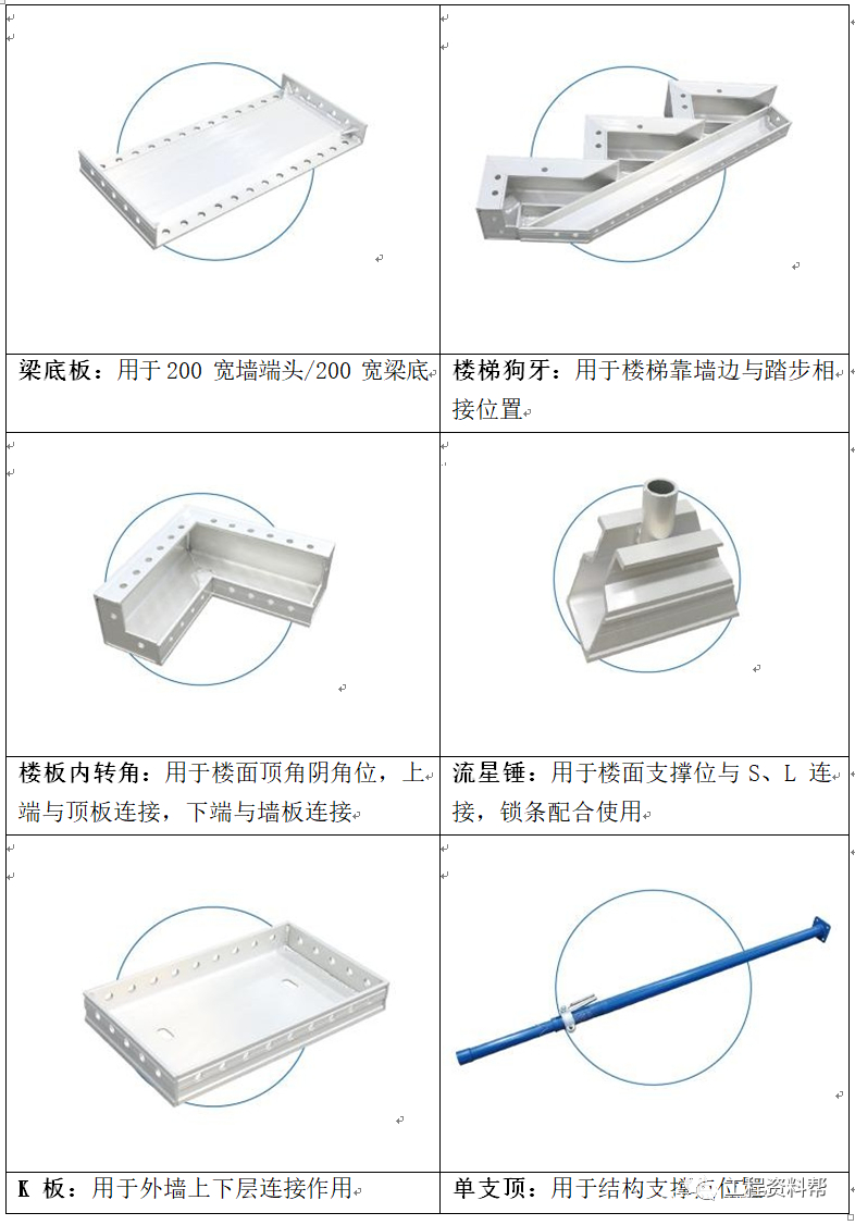
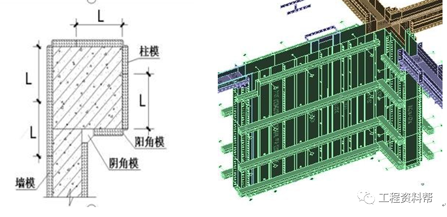
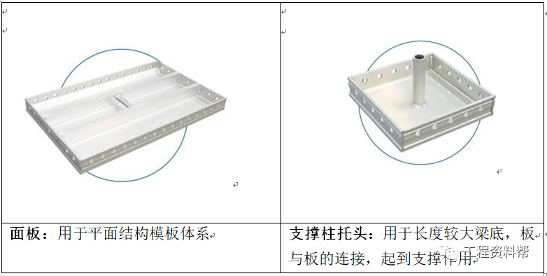
Table 3.1.1 diagram of aluminum alloy formwork accessories Please click to input picture description (up to 18 words) Please click to input picture description (18 words at most) table 3.1.1 aluminum alloy template accessories chart 3.2 Wallboard system the standard wallboard width of our company is 500mm, which adopts the installation form of direct connection between wallboard and roof corner template (roof C groove)
. 
The height of external wall receiving board (k board) is increased by 50 mm, and the height of internal and external wall boards is the same
. 
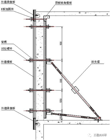
The wallboard is reinforced by back ridge (inner 4, outer 5) and pull bolt
. 
The maximum horizontal distance of pull bolt is 1000mm, and the vertical distance is 250mm, 550mm, 800mm and 900mm
. 
The connection between single formwork is made by pin, which is fastened by pin piece
. 
The overall stability of the wallboard is supported by an adjustable inclined support, which is fixed on the ground with expansion bolts (or embedded rings), and the other end is fixed on the back ridge with bolts, which can maintain the overall stability of the formwork and adjust the verticality of the formwork
. 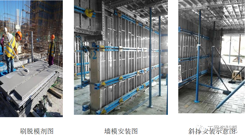
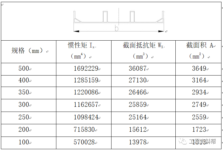
Figure 3.2.1 wall formwork design diagram 3.2.2 wall formwork section diagram 3.2.3500 wide typical formwork Section 3.3 The standard size of aluminum alloy formwork at the bottom of top plate system is 500×1200 mm, and the formwork is adjusted according to the actual structure size
. 
The floor is provided with a 100 mm wide beam (commonly known as keel), and the maximum spacing of the supporting poles at the bottom of the standard plate is 1200 mm × 1300mm。 Fig
. 
3.3.1 schematic diagram of top plate template matching Fig
.
3.3.2 schematic diagram of connection between bearing beam and support head Please click to input the picture description (18 words at most) figure 3.3.3 schematic diagram of support section of roof template on bearing beam / support head Figure 3.4 The standard layer height of this project is 2.9m
.
The beam bottom adopts the design mode of early dismantling head, the support spacing of the beam bottom is not more than 1200mm, the width of the early dismantling head is 150mm, and the aluminum formwork of 1000mm is used between the early dismantling heads
.
Fig
.
3.4.1 elevation diagram of beam formwork assembly Fig
.
3.4.2 horizontal diagram of beam formwork assembly Fig
.
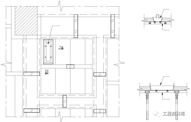
3.5 column formwork system column formwork design principle is the same as wall formwork, but the following points should be paid attention to in column formwork design: 1
.
When the column is an independent column, the formwork shall be matched according to the column size, and the single column formwork size shall be designed to be the same as the wall standard plate size as far as possible, so that the formwork can be universal
.
Avoid a lot of changes to the formwork due to the change of column size in the later stage
.
And the formwork of the column itself should be designed as the same size as possible
.
Fig
.
3.5.1 design of formwork for single column 1
.
When connecting the wall and column, it should be noted that the junction of the wall and column should be set as a whole plate, and the gap between the formwork should not be set here
.
Fig
.
3.5.2 design of wall column formwork Fig
.
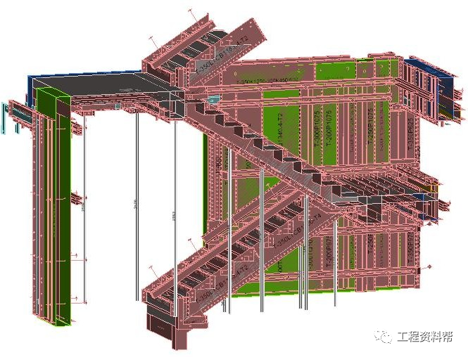
3.6 stair formwork system the stair formwork includes step formwork, bottom formwork, bottom keel, wall formwork, stair side formwork, side sealing plate and other components
.
In order to ensure that the stairs will not deform, the back ridge is generally used to reinforce the upper side and bottom of the step formwork, and the single support is used at the bottom to ensure that the stairs will not deviate and deform
.
The detailed reinforcement style is shown in the die drawing
.
Please click to input the picture description (18 words at most) Fig
.
3.6.1 stair template section Fig
.
3.7 the place where the formwork is lowered is generally distributed in the toilet and balcony
.
The angle aluminum is used to fix the angle of the formwork
.
When the settlement height is less than 100 mm, the angle iron or square steel is used as the formwork
.
If there is upside down structure around the downcomer, the external corner formwork can be used to connect the downcomer with the upside down structure to fix the downcomer and prevent the downcomer from shifting or floating during concrete pouring.
.