
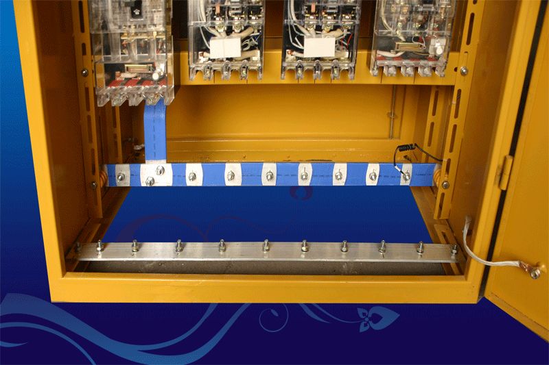
The distribution box (cabinet) and switch box shall be provided with n-line and PE line terminal boards, and the incoming and outgoing lines must be reliably connected through the terminal board
.
The leakage circuit breaker in the main distribution box shall be products for distribution protection
.
Schematic diagram of switch box of ground pump and other large equipment electrical system diagram of ground pump and other large equipment two Kdm1 or DZ20 (above 160A, 380V) series transparent molded case circuit breaker is set in the power switch box of tower crane and other equipment as the control switch, and dz20l series transparent leakage circuit breaker or lbm-1 series leakage circuit breaker is configured; The terminal block of PE line is 3 connecting bolts
.
One is the connection point of PE line into the box and the other is the connection point of repeated grounding
.
The product of rated leakage action current and rated leakage action time of leakage protection device shall not be greater than 30mA
. 
The connection between PE line and terminal board must adopt electrical connection
. 
temporary power management (I) operation electricians on the construction site must work with certificates after passing the examination according to the current national standards( 2) All kinds of power users must pass relevant safety education and training and technical disclosure, master the basic knowledge of safe power use and the performance of the equipment used, and work after passing the examination( 3) The installation, patrol inspection, maintenance or removal of temporary electrical equipment and lines must be completed by electricians and supervised by personnel( 4) Regulations on temporary power consumption organization design: 1) if there are 5 or more temporary power consumption equipment on the construction site or the total capacity of the equipment is 50KW or above, the power consumption organization design shall be prepared; Otherwise, safe power use and electrical fire prevention measures shall be formulated
. 
The layout of the distribution room shall meet the following requirements (I) the width of the operation channel on the front of the distribution cabinet
. 
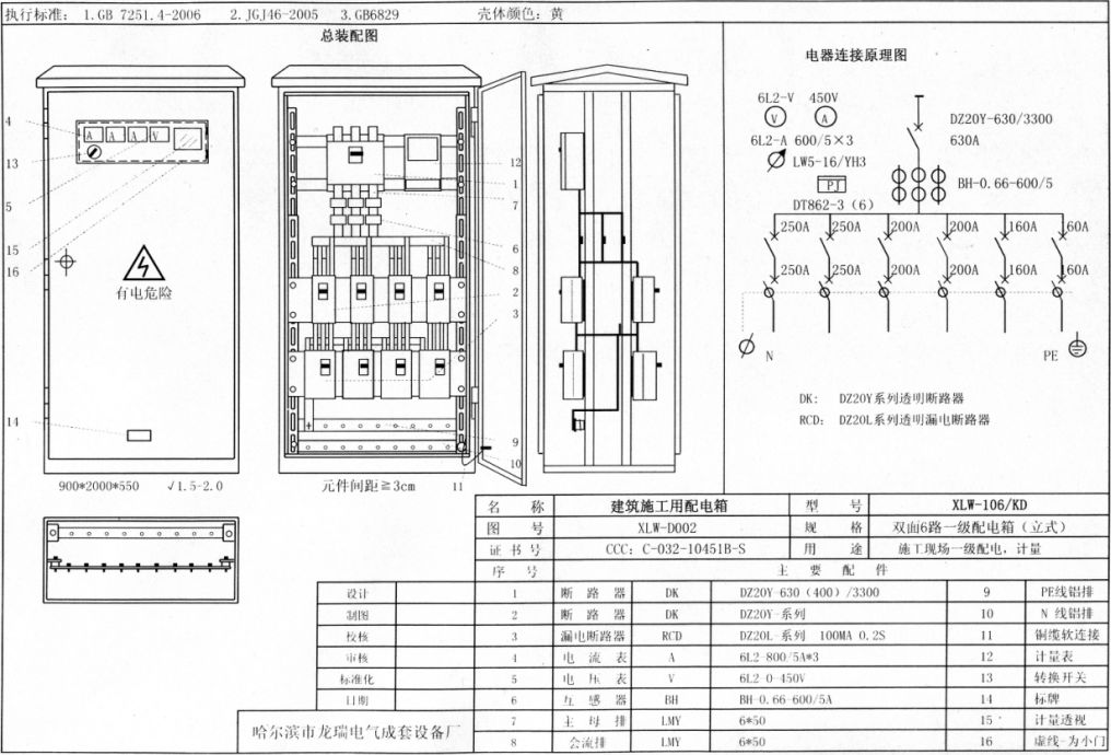
Example 1 of three-level distribution setting: 400a-630a DZ20 transparent molded case circuit breaker with isolation function is set in the main distribution box (cabinet) as the main switch, 4-8 circuits are set in the shunt, DZ20 series 160a-250a transparent molded case circuit breaker with isolation function is used, and dz20l (DZ15L) transparent leakage switch or lbm-1 series are equipped as leakage protection devices to make it have undervoltage, overload, short circuit, leakage Open phase protection function, and watt hour meter, voltmeter, ammeter and two groups of current transformers are equipped at the same time

The number of electrical connection points shall be 2 more than the number of circuits in the box
. 
Schematic diagram of lighting switch box electrical system diagram of lighting switch box note: the leakage circuit breaker in the switch box must select products with rated leakage action current not greater than 30mA, rated leakage action time not greater than 0.1s, current quick break and electromagnetic motor guarantee
.
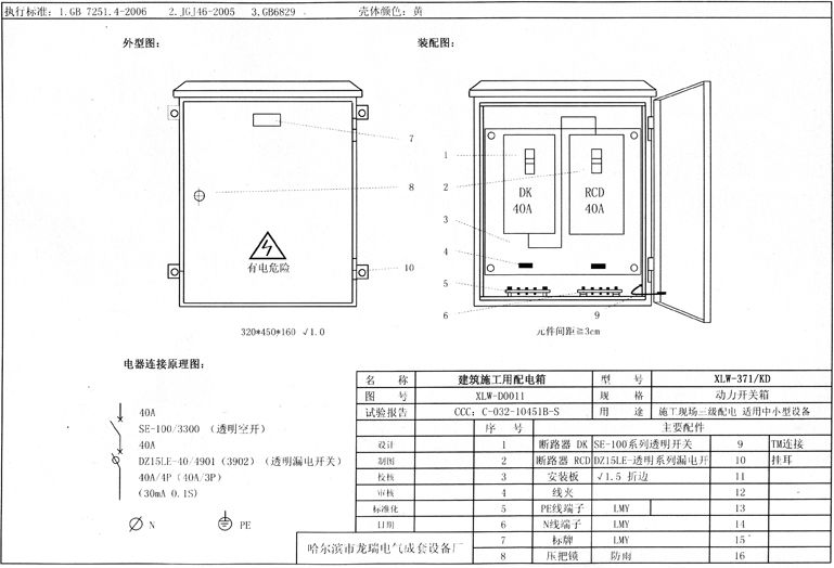
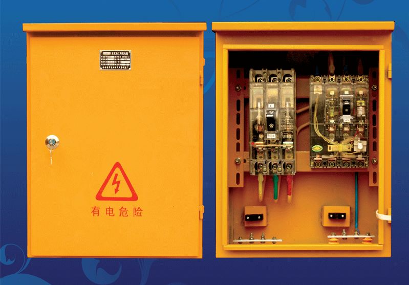
Schematic diagram of power switch box below 40A terminal contact and electrical contact connection diagram of power switch box electrical system diagram of power switch box for equipment below 40A four The switch box of electric equipment above 5.5kW selects the control switch and leakage circuit breaker according to the rated capacity of the controlled equipment
.
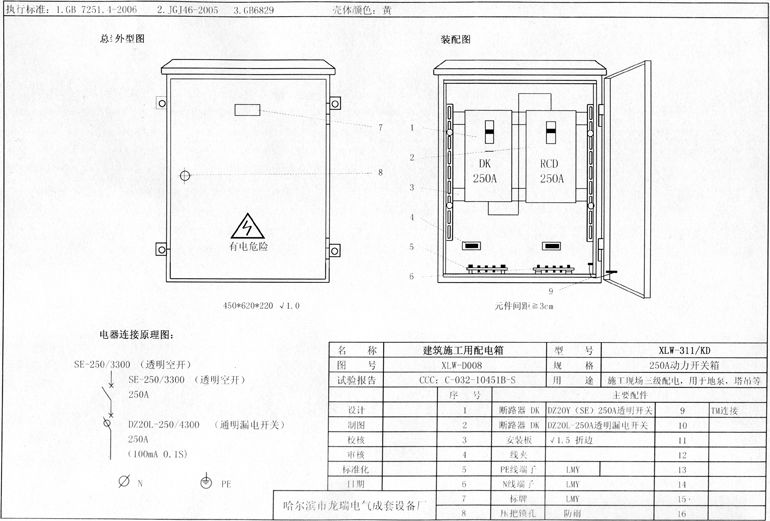
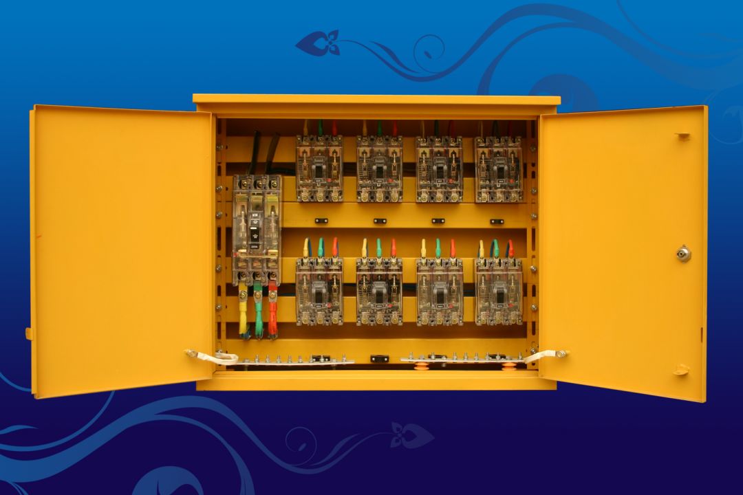
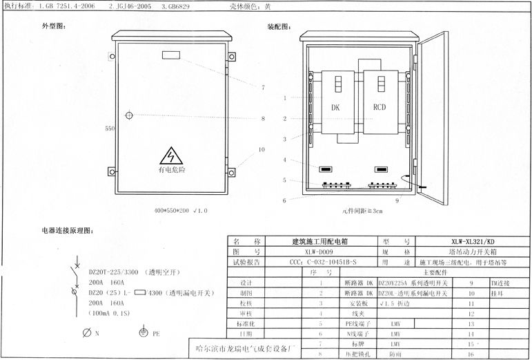
Distribution box schematic diagram distribution box n-line terminal board contact diagram distribution box PE line terminal board contact diagram distribution box electrical system diagram including tower crane circuit distribution box schematic diagram (terminal board contact and electrical connection point diagram are the same as above) including tower crane circuit distribution box system diagram two Schematic diagram of 6-8 circuit distribution box excluding lighting circuit distribution box 6 circuit distribution box including tower crane circuit (terminal board contact and electrical connection point diagram are the same as above) 8 circuit distribution box system diagram 6 circuit including tower crane circuit distribution box system diagram 3 switch box (one machine, one switch, one leakage and one box) one Kdm1 or DZ20 (above 160A, 380V) series transparent molded case circuit breaker is set as the control switch in the power switch box of large equipment such as ground pump, and dz20l series transparent leakage circuit breaker or lbm-1 series leakage circuit breaker are configured; The terminal block of PE line is 3 connecting bolts
. 

S
.
Schematic diagram of power switch box of tower crane and other equipment system diagram of power switch box of tower crane and other equipment three DZ20 (20-40a, 380V) or se, kdmi series transparent molded case circuit breakers are set in the switch box of electrical equipment below 3.0kw as the control switch, dz15le (20-40a) or lbm1 series transparent leakage circuit breakers are configured, and the PE line terminal block is 4 connecting bolts
. 


The erection of distribution box shall meet the following requirements (I) the vertical distance between the center point of fixed distribution box and switch box and the ground shall be 1.4 ~ 1.6m
.
If there are protruding parts of the building structure in some places, the channel width at this point can be reduced by 0.2m( 3) The width of maintenance channel on the side of distribution cabinet shall not be less than 1m( 4) The distance between the ceiling of the distribution room and the ground shall not be less than 3m
.
The n-line in the incoming and outgoing lines must be connected through the n-line terminal board; The PE line must be connected through the PE line terminal board
. 
The single row or double row back-to-back layout shall not be less than 1.5m, and the double row face-to-face layout shall not be less than 2m( 2) The width of the maintenance channel behind the distribution cabinet shall not be less than 0.8m for single row arrangement or double row face-to-face arrangement, and not less than 1.5m for double row back-to-back arrangement
.
It is better to select the rated leakage action current of 75-150ma, the rated leakage action time is greater than 0.1s and less than or equal to 0.2S, and the action time is delayed action type
. 
The control switch is DZ20 (Se or kdm1) series transparent molded case circuit breaker, and the leakage circuit breaker is DZ15L series transparent leakage circuit breaker; There are 3 PE wire connecting bolts
. 


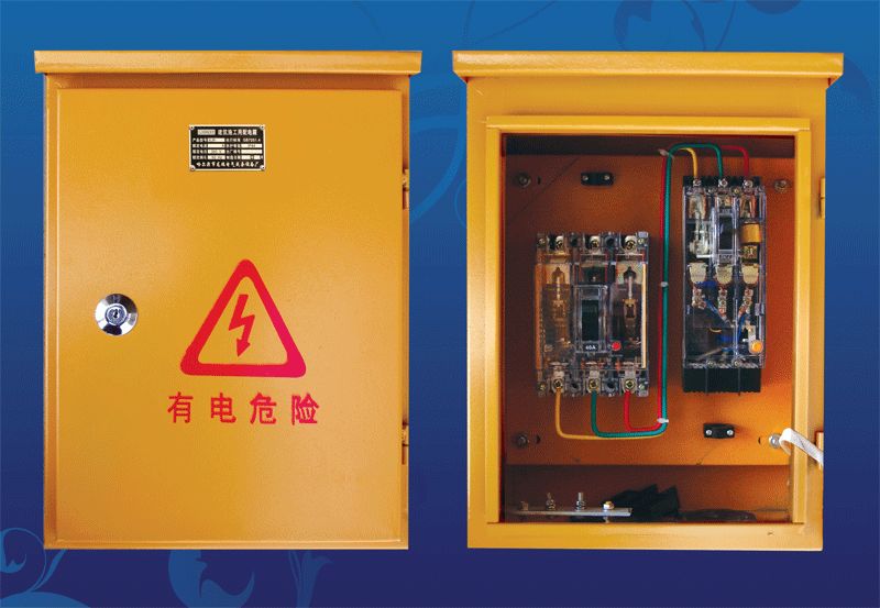
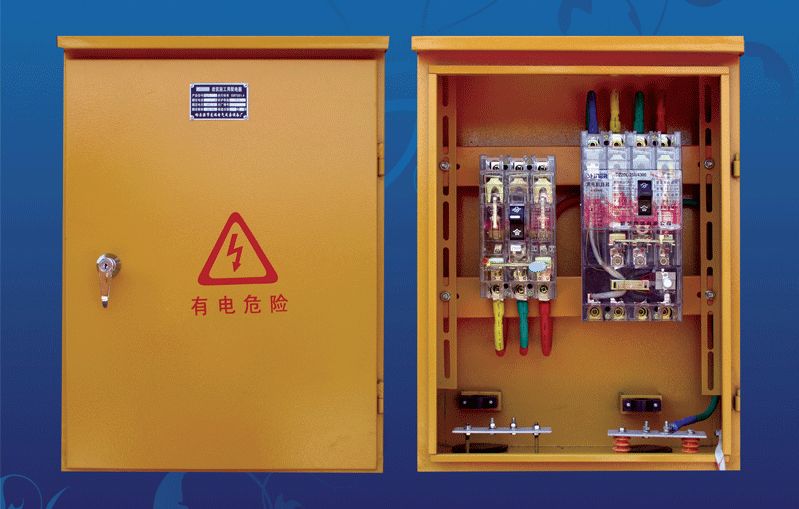
It is suitable for temporary power consumption at the construction site and outdoors, and should meet the use requirements of “three-level distribution, two-level leakage protection, one machine, one switch, one leakage box”
. 
The thickness of the steel plate meets the standard requirements and is durable
.
The vertical distance between the mobile box and the ground is 0.8 ~ 1.6m
.
The n-wire terminal board must be insulated from the metal electrical installation board; The PE line terminal board must be electrically connected with the metal electrical installation board
. 
The distribution box and switch box shall be installed on a firm and stable support( 2) If the distribution box and switch box are within the falling radius of the building or the rotation radius of the tower crane arm, a double-layer protective shed must be built, and isolation measures must be taken【 Attachment] key points of temporary power management for construction I
. 
Source: in case of infringement by Luban alliance of construction engineering, please contact to delete the distribution box (cabinet)
.
The material selection, manufacturing process, selection and configuration of electrical components in the distribution box (cabinet) and switch box shall comply with relevant national standards, and the products shall pass CCC certification
.
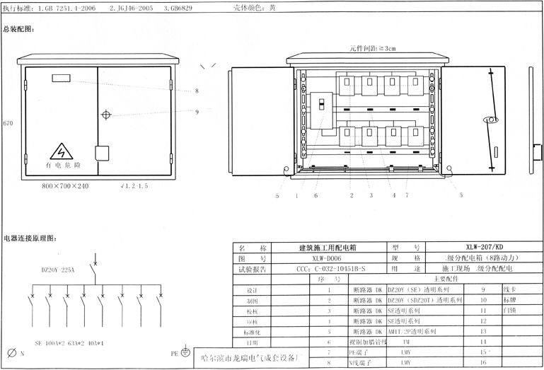
Schematic diagram of general distribution cabinet terminal board contact diagram of general distribution cabinet door electrical connection point diagram of four circuit distribution cabinet electrical system diagram of six circuit distribution cabinet electrical system diagram of eight circuit distribution cabinet electrical system diagram of two circuit distribution cabinet one A 200a-250a DZ20 series transparent molded case circuit breaker with isolation function is set in the distribution box including lighting circuit (power circuit and lighting circuit shunt distribution) as the main switch (suitable for the circuit breaker set in the shunt of the main distribution box); DZ20 or KDM-1 transparent molded case circuit breaker is used as power shunt and lighting shunt control switch; Each distribution circuit adopts DZ20 or KDM-1 transparent molded case circuit breaker as the control switch; PE line connecting bolts and N line connecting bolts shall be configured according to actual needs
.
2) For decoration works or other special construction stages, a single construction power consumption scheme shall be supplemented( 5) The temporary power use organization design and change must be prepared by electrical engineering technicians, reviewed by relevant departments, approved by the technical director of the enterprise with legal personality and signed by the on-site supervisor.
.
Schematic diagram of switch box of equipment above 5.5kW electrical system diagram of switch box of equipment above 5.5kw five The lighting switch box is equipped with kdm1-t / 2 (20-40a) circuit breaker, dz15l-20-40 / 290 leakage circuit breaker and 3 PE line bolts
.
The shell of the distribution box (cabinet) is made of cold-rolled steel plate, rainproof, dustproof and outdoor
.