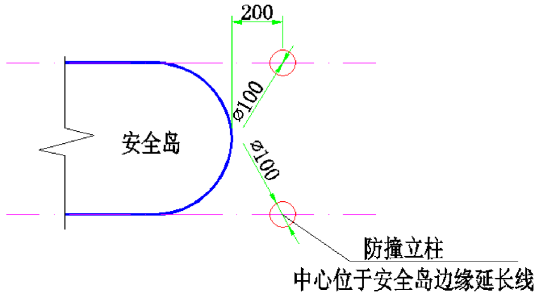
Safety barriers shall be set around the equipment, as shown in the figure below, and anti-collision columns shall be set on the edge extension lines at both ends of the safety island
.
You can increase the infrared radiation detection mode and the number of coil turns to improve the detection reliability, or adopt the radar detection scheme
.
When multiple feeders are required or the feeder is longer (more than 50m), the wiring shall be carried out as close to the offline coil as possible
.
the trigger distance, which can be adjusted according to the situation of 3.5-5m)
.
The coil wire placed in the slot shall be placed loosely according to the natural state without stress, and shall be pressed to the bottom of the slot one by one
.
2、 Construction specification of ground induction coil the coil slot shall be cut on a solid and firm subgrade to avoid the damaged road surface; Concrete pavement shall avoid joint; The thickness of bricks shall be confirmed in advance in the construction scheme of laying bricks on the coil
.
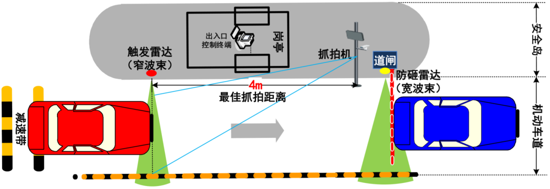
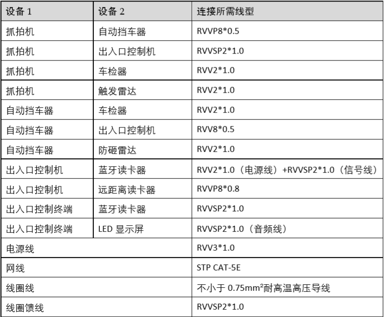
The entrance and exit system of the parking lot is mainly composed of camera, gate, gate radar, entrance and exit control terminal, coil, vehicle detector and other equipment, which is responsible for routine control and charging of entrance and exit vehicles
.
At the end where the feeder shield wire is connected to the vehicle detector, the shield layer must be grounded
.
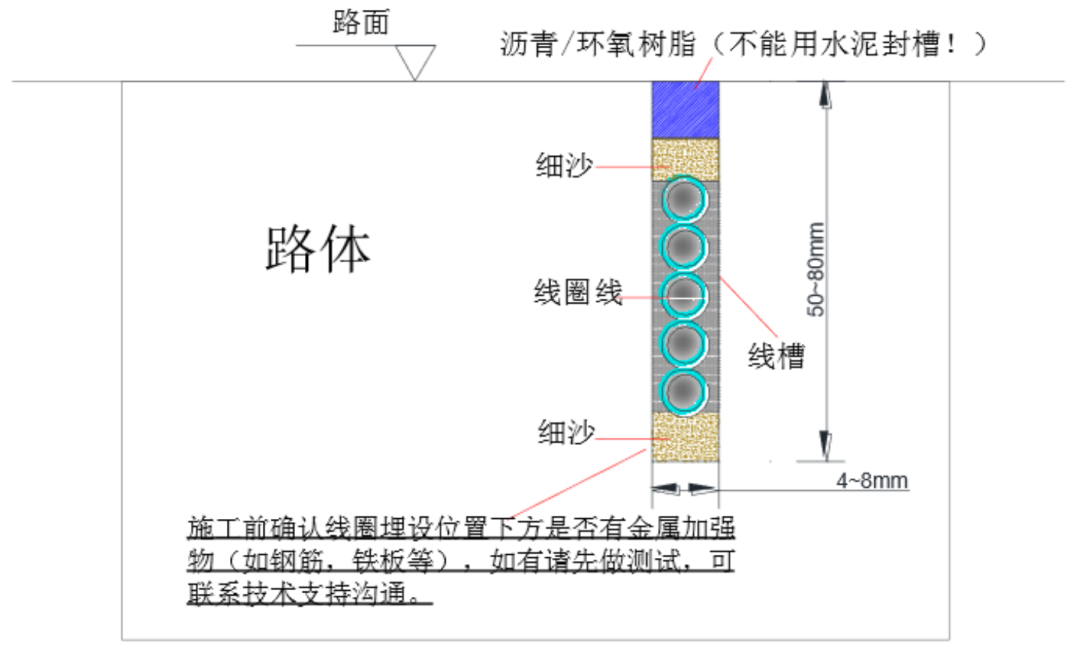
After the coil and lead are compacted in the trunking, a layer of 5mm thick fine sand shall be paved to prevent the coil shielding layer from melting at high temperature
.
Coil width: for ordinary vehicles, the coil width is 1m; If there are special vehicles such as trucks (high chassis), trailers (the middle space does not exceed the coil width), oil tankers, etc., the coil width is 1.5m
. 
If galvanized steel pipe (JDG pipe or KBG pipe) is used, the pipe spacing with signal line can be reduced to 0.1M
.
Multi core cable shall not be used for coil feeder, but 2-core shielded twisted pair shall be used, and one pair of twisted pair shall be used for each coil
.
When installing the equipment, the effective field of view of the camera shall not be blocked
.
The connection between coil feeder and lead must be welded, wrapped with waterproof tape and insulating tape and placed in waterproof junction box
.
The chassis shall be firmly fixed without looseness or swing
.
The buried pipe depth shall not be less than 0.1M
.
Continue pouring for 3 times until the pouring surface of the trunking is flush with the road after cooling and solidification
. 
0.6m * 0.6m hand shaft shall be built every 10m of embedded line pipe
.
You can contact our company in advance to obtain the baseline scheme drawings and complete the construction drawing design with reference
.
Before pouring concrete on the safety island, the embedded pipe must be fixed according to the construction drawings and equipment routing requirements
.
2、 Construction specification: Construction of safety island and ground induction coil I
.
In case of T-shaped driving track or wide lane, double camera shall be arranged for multi angle capture, as shown in the figure below
.
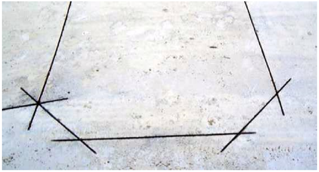
In the actual cutting process, each side of the rectangle cannot be cut to the end to prevent the whole triangle from falling off and warping out of the road when cutting chamfer
.
There shall be no fracture or deformation at the bend of the pipe, and there shall be no foreign matter in the pipe
.
Example drawing of trunking chamfer cutting lead slot: lead slot to be cut to the safety island or roadside handwell
. 
The horizontal distance from the position of the camera to the trigger coil is 4m (i.e
. 
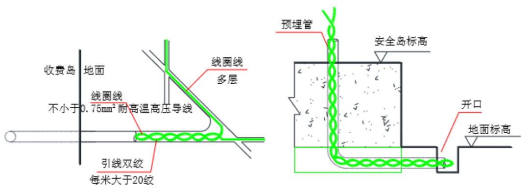
Step 3 coil wire laying (wire specification: fvn49 / 0.26 or not less than 0.75mm) ² After cleaning and drying the trunking, lay a layer of 5mm thick fine sand at the bottom (to prevent the hard edges and corners at the bottom of the trunking from cutting the wire)
. 
If necessary, please contact our technical support to confirm the implementation scheme
.
As shown in the figure below
.
The installation angle of the camera shall ensure that the license plate captured can be straightened when the vehicle head reaches the trigger position
.
In this issue, let’s learn about the construction specifications and precautions of the next parking lot, taking the construction of Haikang parking lot as an example
.
For special scenes or complex environments, please communicate with Haikang technical support in time after the survey“ The “construction scheme design” link includes the design of construction drawings
.
The connector must ensure low resistance, and the external insulation degree shall not be worse than that of the original cable
.
3、 Construction steps of ground induction coil: Step 1 Trunking positioning: determine the trunking position according to the construction scheme and drawings, and set out and position at the corresponding position in advance
.
There is a reinforcing mesh under the laying position of the local sensing coil, which will interfere with the coil detection
.
When outgoing from the safety island or roadside manhole, a 1.5m long wire head is reserved (after wiring, the excess is cut off)
.
1、 Attention to system construction process: please pay attention to the “engineering survey” link
.
Both ends of the pipe shall be blocked before pouring concrete
.
Layout diagram of Dual Camera 3
.
cement foundation (or safety island) must be built at the installation place of automatic car stopper, entrance and exit control machine, entrance and exit control machine and automatic car stopper, and shall not be installed in low-lying areas to prevent ponding from adversely affecting the equipment
.
The fuselage of entrance and exit control machine and automatic car stopper shall be perpendicular to the horizontal plane, and its maximum inclination angle shall not be greater than 1 °
. 
After cooling and solidification, the pouring surface in the groove will sink
.
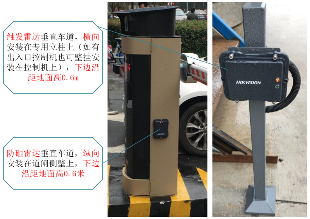
Gateway radar consists of “trigger radar” and “anti smash radar”.
.
Coil construction section the coil leads are twisted in pairs clockwise (more than 20 twisted per meter) and put into the lead slot
Strong and weak current cables must be threaded separately: when PVC pipe (or PE pipe) is used for power line threading, the pipe spacing with signal line shall not be less than 0.15m
.
2、 According to the construction drawings, determine the installation position of the camera at the entrance and exit, mark the installation hole position of the camera column base on the safety island, fix the vertical rod through the expansion screw, and install the camera
.
5-6 turns of wire shall be wound clockwise in the coil slot (operate according to the site conditions)
.
Check whether the sensing value is 100 with a multimeter μ H—300 μ Check whether the voltage value is less than 2mV (AC millivolt gear of multimeter is adopted), otherwise it needs to be rectified
.
There shall be no large amount of metal within 0.5m around the coil, such as manhole cover, telescopic door guide rail, drainage ditch, etc; There shall be no more than 220V power supply circuit within 1m around
.
According to the construction drawings and product installation guidelines, determine the installation position of the chassis, mark the hole position, open the hole with a drill and fix it with bolts
.
Coil long side: determined according to the lane width, it is required to be 0.6-1m away from the lane edge and the total length shall not exceed 5m
.
When entering and leaving the mixed traffic lane, the anti smashing coil shall be placed in the middle of the road gate rod; When entering and leaving the separation lane, the anti smashing coil shall span under the gate rod in the ratio of 3:7 (7 in the departure direction)
. 
Note: it is recommended to lock the road gate when passing through engineering vehicles such as excavators and bulldozers
.
Because the leads must be twisted in pairs, the lead slot is usually wider than the coil loop slot
.
Note: ensure that the wire (coil wire and lead wire) is free of damage, the insulating layer is free of damage, and there is no joint in the middle
.
Coil incoming plan & coil incoming section step 4 Feeder laying (when the coil lead twisted pair exceeds 10m, the feeder shall be arranged)
.
The construction site of any project must have corresponding construction drawings as the basis for construction guidance
.
3、 Equipment installation specification I
.
Step 5 groove sealing: after laying with quick setting epoxy resin or melted hard asphalt wire, it is necessary to detect the sensing value and voltage
.
The trunking shall be poured with melted hard asphalt or quick setting epoxy resin
. 
The distance between two ground induction coils connected to different vehicle detectors shall not be less than 1.3m, and the distance between two ground induction coils connected to the same vehicle detector shall not be less than 0.5m
.
Step 2: slot cutting: slot specification: slot cutting width 4-8mm, depth 50-80mm; The slotted section shall be neat, and the depth and width of each trunking shall be uniform
.
Chamfering: the sharp corners of the trunking shall be chamfered to prevent damage to the coil
.
safety island fabrication specification: safety island shall be fabricated according to the size of safety island or equipment foundation in the construction drawings
.
Seal the two ends with adhesive tape to prevent moisture from entering
.
A safe distance shall be reserved between the equipment to ensure that the chassis door can be opened normally; The lifting and landing of automatic car stopper rod shall be unobstructed
.
The outlet of the embedded pipe shall be strictly positioned according to the equipment installation position, and arranged neatly and compactly according to the size of the equipment installation foundation area
.
Gateway radar
.