During the curing period, thread the 0# section of web beam and top plate beam steel strand, and install the anchorage and Jack.
Internal model: the inner mold is assembled by steel wood combination template.
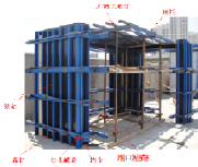
0# section side formwork and reinforcement: the side formwork mainly adopts hanging basket external formwork, and the shaped formwork is adopted for the widened section in the middle.
Fix the longitudinal corrugated pipe: set the longitudinal web corrugated pipe and weld the positioning net.
The elevation shall be observed again after unloading the preloading load according to the loading level.
The pouring height of each layer of concrete shall not exceed 50cm.
After the foundation is under the action of the previous level of load and the settlement speed of the foundation is stable, the next level of load can be applied, especially in the later stage of loading, The loading rate shall be strictly controlled to prevent the shear failure of the foundation due to excessive and rapid overall or local loading.
In the process of preloading after each loading level, it shall be observed once every 24 hours on average until the settlement speed has decreased to 0.5 ~ 1.0mm/d.
During loading, pay attention to the size of the loading weight and the loading rate to make it adapt to the strength growth of the foundation.
The support step along the beam height direction is 120cm, and the square timber is arranged as 30cm in the transverse bridge direction.
Accurate measurement shall be carried out during preloading, It is necessary to measure the elastic deformation value and foundation settlement value generated by the support under the load of the beam section, superimpose the elastic deformation value and foundation settlement value with the pre camber required to be set due to other factors proposed in the construction control, calculate the pre camber that should be used during construction, and adjust the bottom formwork elevation according to the calculated pre camber.
In order to facilitate workers to go up and down, escalator channels are set up and protected with dense mesh nets to ensure the safety of workers up and down.
The bearing platform size of the main pier of a bridge is 10.6m × 14.6m, while 0# block support size is 10.6m × 11.2m, and the size of main pier bearing platform is 9.0 × 11.0m, the top surface of the bearing platform can be used as the support foundation, and 1m width is added on both sides of the transverse bearing platform as the sidewalk support foundation.
(2) The theoretical elongation value △ L (mm) of steel hinge wire is calculated according to the following formula: △ L = (PPL) / (APEP), where: PP – average tensioning force of steel hinge wire (n); L – length of steel hinge line (mm); AP – sectional area of steel hinge wire (mm2); EP – elastic modulus of steel hinge wire (n / mm2).
2、 Calculation of prestressed tendon tensioning data (1) the average tensioning force of prestressed steel strand is calculated according to the following formula: PP – average tensioning force of steel strand (n); P – tensile force at the tensioning end of prestressed reinforcement (n); X – duct length from tensioning end to calculated section (m); θ— Sum of included angles (RAD) from the tensioning end to the tangent of the duct part of the calculated section curve; K – influence coefficient of friction caused by local deviation per meter of duct; μ— Friction coefficient between prestressed reinforcement and duct wall.
The elevation of the bottom formwork shall be observed once before preloading.
The pouring sequence of beam concrete is shown in the figure.
Each support outside the 0# section shall be erected as a working platform.
The concrete pouring sequence of the same section is first the web root, then the bottom plate, then the upper part of the web, and finally the top plate.
Pouring 0# section concrete: after passing the inspection of the supervising engineer, the concrete is transported to the 0# section by concrete pump truck.
See note for support calculation.
The 9015 and 6015 standard template is adopted in the straight section of the inner mold.
Lift the side formwork to the pier top with a crane, support it on the support, and temporarily fix the side formwork on both sides of the pier body with a chain fall; Then adjust the elevation, perpendicularity and position of the formwork with a jack, and finally fix it completely.
Concrete curing: after the initial setting of concrete, the top surface shall be covered with Geotextile for moisturizing, and the concrete shall be watered and cured in strict accordance with the construction specifications to ensure that the concrete does not crack.
The side formwork adopts hanging basket formwork, the bottom formwork and internal formwork adopt steel wood composite formwork, and the top of the support is 14 I-steel longitudinally and 12 horizontally from bottom to top × 12cm square timber, and the bottom end of the support is laid longitudinally for 15 minutes × 15cm sleeper.
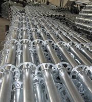
The standard bowl buckle scaffold with diameter of 48mm and wall thickness of 3.5mm is used for support erection.
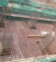
Binding bottom plate, web plate and diaphragm reinforcement: while adjusting the side formwork, quickly bind the bottom plate, diaphragm plate and web reinforcement, and install the plug wood formwork at the same time; Thick reinforcement shall be added in the middle of the diaphragm to support the inner formwork of the diaphragm.
During loading, the load is divided into three levels according to 50%, 100% and 120% of the design load (sand bag or reinforcement, steel strand and crane hoisting).
The camber shall be set as required, the elevation of the bottom formwork shall be adjusted, and the wooden wedge shall be used for adjustment and reinforcement.
A positioning net shall be set every 1.0m on the straight section of the straight beam, and it shall be properly densified to no more than 0.5m in the horizontal bending and vertical bending sections of the tendon.
The construction shall be carried out according to the layout of longitudinal and transverse beams of the support.
In order to prevent the collapse of prestressed tendons in the bottom plate and web, anti collapse reinforcement with diameter of 12 deformed steel bars and spacing of 100mm shall be set.
The tensioning stress shall be carried out after the strength and elastic modulus of beam concrete reach 90% of the design value, and the age of beam concrete shall not be less than 5 days during tensioning..
The pouring sequence: pouring from the middle to both ends, horizontal layers, symmetrical webs on both sides and continuous pouring.
The calculation of elongation and tensioning force shall be reported to the supervising engineer for approval before prestressed tensioning according to the test data and relevant specifications.
(1) The support erection 0# section adopts the turnbuckle type full hall support erection.
1m * 1m precast blocks are used for loading.
Tensioning and grouting: before tensioning, conduct friction test on the prestressed pipeline and adjust the tensioning force according to the test results.
(3) The bottom formwork shall be installed for the main construction of section 0 # and the bottom formwork shall be set with camber: the bottom formwork of section 0 # shall be laid with 9015 and 6015 steel formwork.
(3) Actual elongation of steel hinge wire tensioning △ L (mm) = △ L1 + △ L2, where: △ L1 – measured elongation value from initial stress to maximum tensioning stress (mm) △ L2 – calculated elongation value below initial stress (mm), using the elongation value of adjacent stages.
The longitudinal spacing of scaffold poles under the bottom formwork is 30cm, and the transverse spacing is respectively set according to the corresponding position of box girder: 60cm under the bottom plate, 30cm at the web, 90cm at the flange plate.
Binding of top plate reinforcement: after the internal formwork is erected, the bottom reinforcement of top plate shall be bound immediately; Arrange the longitudinal prestressed tendon bellows and transverse prestressed tendon bellows of the top plate; Bind the roof reinforcement and adjust the spacing of vertical prestressed reinforcement.
The preloading load shall be 120% of the design load, and the load holding time after full load shall not be less than 24h.
During loading, technicians shall control the loading weight and loading position on site to avoid excessive error affecting the observation results.
According to the force distribution on the support after box girder pouring, they are lifted to the top of the support by crane and placed manually.
1、 0# section construction process: support assembly is completed → support preloading → lifting the outer formwork in pieces → installing the bottom formwork → binding the bottom slab reinforcement → installing the longitudinal prestressed pipeline of the bottom slab → binding the web reinforcement → installing the longitudinal prestressed pipeline of the web → installing the vertical prestressed reinforcement and pipeline → installing the inner formwork → binding the top slab reinforcement → installing the longitudinal Transverse prestressed pipeline → install transverse prestressed reinforcement → set up concrete pouring platform → pouring concrete → curing → formwork removal → threading steel strand → pre stress application → grouting.
The positioning net adopts hpb235 diameter 8 plain round reinforcement.
(2) Support preloading in order to prevent concrete cracks in the poured beam section due to support subsidence and ensure that the alignment of the beam section is consistent with the design, the support shall be preloaded in addition to improving the stiffness of the support and reducing the deformation of the upper structure of the support.
The bamboo board and the 5cm thick plank are combined in the circular arc chamfer, then the position and elevation are adjusted, and the support is strengthened and strengthened.
The maximum settlement of foundation shall not exceed 10mm / D; The horizontal displacement shall not be greater than 4mm / d.


