After the channel steel of the cantilever layer is fixed, the socket and buckle type external frame upright can be placed in the U-shaped groove of the channel steel with an adjustable bottom support, and then after the first row of shelves are erected according to the normal construction process, the cross bar between the upright and the upright on the channel steel surface shall be set immediately before continuing to be erected upward.
At the disconnection point of the socket type disc buckle outer frame, the ordinary steel pipe is used to connect with the disc buckle vertical rod in each horizontal step.
See Figure 4.2.1 below for the anchoring diagram of embedded bolts of cantilever outer frame.
During the removal of socket and turnbuckle outer frame, the operation area shall be divided, fences or warning signs shall be set around, and special personnel shall be assigned to command on the ground.
The load acting on the cross bar is transmitted to the vertical bar through the turnbuckle.
The joint design takes into account the role of self gravity, so that the joint has a reliable two-way self-locking capacity.
7.
Scope of application: applicable to external protection and decoration of construction engineering structures.
The safety net shall be set outside Inside the vertical pole, the tensioning height shall not be less than 1.2m higher than the construction surface.
It is strictly prohibited to keep unstable rods on the frame body.
4.2.2-1 schematic diagram of cantilever external frame section steel laying node.
When releasing the buckle related to another person, it is necessary to notify the other person first to prevent falling.
1.
Non staff are strictly prohibited to enter.
4.2.3-1 erection section of cantilever outer frame 5.
If the height difference is greater than 2 steps, wall connecting parts shall be added for reinforcement.
4.
The bell and spigot type disc buckle outer frame shall be continuously provided with diagonal tie rods for every five spans along the longitudinal direction of the frame body.
In the process of assembly and disassembly, workers can complete all operations with a hammer.
It is strictly forbidden to remove the whole or several layers of wall connecting parts before removing the scaffold.
4.2.3-2 for the connection diagram at the disconnection point of the socket type disc buckle outer frame.
The removal of socket and disc buckle outer frame must be approved by the project department, and the professional person in charge shall make safety technical disclosure to the operators.
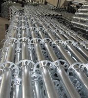
The three process principles are composed of vertical rod, cross rod, inclined pull rod, adjustable bottom support and other components.
The wall connecting parts shall be removed layer by layer with the scaffold removal progress.
construction process flow and key points of operation 4.1 construction process flow construction preparation → embedded precast bolts → concrete pouring → laying I-beam → fixing I-beam → laying channel steel → scaffold erection → hanging safety protection net 4.2 “key points of operation” 4.2.1 two precast bolts shall be used for embedded precast bolts Φ 20 thin wire bolts are welded on 5mm thick steel plate.
The first construction method features a specially designed plug-in plate and locking structure.
After practical application, the external wall socket and disc buckle steel pipe scaffold has the characteristics of convenient assembly and disassembly, flexible construction, good appearance image, energy conservation and environmental protection.
When removing the socket and disc buckle outer frame, the high-altitude operators must wear safety helmets, fasten safety belts and wear soft soled shoes.
If the steel pipe cannot be embedded in the wall connecting position, screw holes shall be used for reinforcement, and all wall connecting parts must be painted with red paint.
It is strictly prohibited to remove up and down at the same time.
Before binding the reinforcement of the cantilever layer, first place the center line of the section steel on the formwork according to the designed step distance, and then fix the prefabricated bolt parts on the formwork with iron nails.
The vertical net shall be bound firmly with the cross bar and vertical bar with iron wire.
Fig.
Multidirectional connection makes the frame flexible and manual construction more efficient.
Before the removal of large scaffolds, the reserved loading platform shall be reinforced first to ensure its integrity, safety and stability after removal..
The barrier hook pedal, cross bracing, diagonal bracing and cross bar shall be removed first, and shall be carried out in sequence according to the principle of one step and one cleaning.
A flat net shall be set every six layers for protection.
Figure 4.2.2-2 schematic diagram of I-beam through wall node of cantilever outer frame “4.2.3 scaffold erection 1.
3.
4.2.2-2 schematic diagram of cantilever external frame I-beam passing through the wall node).
2.
The components are collision resistant, have excellent appearance quality, and do not need to be painted, which is energy-saving and environmental protection.
The sundries on the scaffold shall be removed before removal.
IV.
The service life of socket and disc buckle outer frame is much longer than that of traditional fastener outer frame, which can generally be used for more than 10 years.
It shall be erected in stages according to the floor, and each erection height must be one step higher than the construction face of the floor (used as guardrail).
At the same time, a novel construction method of external wall scaffold is formed.
The whole frame adopts modular design, with simple structure, simple and fast assembly and disassembly, and there is little bolt operation and loss of scattered fasteners.
The height difference of sectional removal shall not be greater than 2 steps.
Since the development of external wall scaffold in China, fastener steel pipe scaffold is the most widely used, but there are deficiencies in assembly and disassembly, reliability, safety and economy.
The scaffold on the operation layer shall be fully covered with hanging buckle pedals, and the gap between the scaffold and the building shall be horizontally protected with scaffold board or small pocket net, leaving a residual gap of 12 ~ 15cm.
At least three cross fasteners are used for each ordinary steel pipe, and cross braces are continuously set along the vertical direction of the frame.
3.
Figure 4.2.3-2 schematic diagram of connection at the disconnection of socket and socket type disc buckle outer frame “4.2.4 hang safety protection net.
Extremely high construction and demolition efficiency.
The outside of the mesh and mesh joint must be bound firmly with a gap of no more than 20cm.
Compared with the traditional fastener outer frame, it has obvious effects on assembly and disassembly speed, reliability, safety, labor saving, energy conservation and environmental protection, so it has obvious social and economic benefits.
The wall connecting parts shall be embedded into the shear wall or floor, and shall be arranged in two steps and three spans.
2.
6.
“4.2.5 the removal sequence of socket type disc buckle outer frame is: safety net → toe board → protective railing → hook pedal → vertical diagonal rod → cross bar → vertical pole → wall connecting rod, longitudinal support and diagonal bracing.
5.
II.
The removal of socket and disc buckle outer frame shall follow the principle of top-down, first erection and then demolition, and then erection and first demolition.
4.2.3-1 for the erection section of cantilever external frame.
The center line should be between the two bolts, and then put a plastic sleeve longer than the thickness of the floor plate on the bolt (for the recycling and reuse of the embedded parts), The bolts exposed to the casing shall be wrapped with plastic tape (to prevent mud splashing on the bolts during concrete pouring).
The vertical pole is connected by sleeve socket, the cross pole and diagonal tie rod are clamped into the vertical pole connecting plug plate by rod end and joint, connected by wedge-shaped bolt, and the wall connecting points are set according to the regulations to form a geometrically unchanged structural system, on which the buckle profiled steel plate is laid, and the safety net is hung outside for sealing, so as to provide external protection and decoration for structural construction.
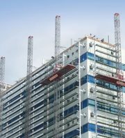
Today, we introduce a construction method of external wall socket and turnbuckle steel pipe scaffold, which is mainly applicable to the construction of floor type and cantilever type external scaffold.
There are no scattered accessories, and the locking structure can ensure the stability of the scaffold.
When removing the socket and disc buckle outer frame, it is necessary to give unified command, echo up and down, and coordinate the action.
If the I-beam passes through the wall, a wooden box shall be sleeved at the I-beam passing through the wall to facilitate the removal of the I-beam after the scaffold is removed (refer to Fig.
If there is only one worker and a hammer, it can also be built.
During the erection of each scaffold, the buckle pedal, vertical inclined rod and wall connecting rod shall be paved, and the cantilever layer and the gap between the cantilever layer and the building shall be paved with wood to form a hard isolation.
A dense mesh safety net shall be set inside the outer pole of socket and socket type disc buckle outer frame for closed protection and fastened with the cross bar.
The socket and disc buckle outer frame has good integrity.
Figure 4.2.1 schematic diagram of embedded bolt anchorage of cantilever outer frame “4.2.2 after laying profile steel concrete, start laying I-beam, correct the access position, and then fix it with double nuts.
See Fig.
6.
4.2.2-1 schematic diagram of cantilever external frame section steel laying node).
The socket turnbuckle has strong shear resistance and is more reliable than the traditional fastener.
4.
After the I-beam is fixed, continuously lay channel steel along the longitudinal direction of the frame, set the u-port of channel steel upward, and weld it on the I-beam on one side (refer to Fig.
Fig.
See Fig.


