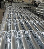
After the foundation section steel is installed, its top should be 10mm higher than the plastered ground; The foundation section steel shall have obvious and reliable grounding.
② In this case, pay attention to the cable arrangement when laying the cable, and the person in charge of on-site construction shall remind the construction personnel at all times.
2.
The wire coming out of the junction box shall be tied with winding pipe or tie tape, such as ①.
First, lay the thickest cable to lay the bottom, and then level the cable.
① When it is difficult to connect the junction box of the motor with the actual position, it can be considered to change the outlet hole of the junction box of the motor to the opposite position.
Pay attention to placing straight binding lines in the bridge at intervals.
The cables in the control cabinet shall be placed neatly.
2.
② ③ if the red circled area is not well tied, the incoming trunking can be broken straight and obliquely.
The ground wire treatment method of the motor shown in this figure.
③ When the main bridge frame of the bridge needs to turn a right angle when entering the power distribution, pay attention to whether the bridge can still be installed, or consider increasing it.
1.
They shall be fixed with clips, and standard parts should be used.
As shown in the figure, the construction drawing when laying horizontal bridge cables shall be tied down at intervals.
Generally, one protective tube shall be used, and one cable shall be threaded through it.
1.
② when there is no hose joint combined with the junction box as shown in, it shall be wrapped with adhesive tape.
This figure shows the motor wiring of a particle system grading screen.
As shown in the figure, the binding wire is good, but the cable marking plate is still missing.
2.
The cable cannot be straight, but it should be aligned as far as possible.
The effect of turning into the trunking shown in the figure.
1.
Please click here ↓↓..
③ All cables shall be arranged on the beam from top to bottom according to the arrangement sequence of the terminal diagram.
① When generating a vertical elbow, it is necessary to consider whether its capacity is enough.
The wiring in the figure is the wrong connection method, and the protective armor of the cable shall be removed before entering the trunking.
① the protective pipe head shown shall be tilted to facilitate the connection with hose with pipe connector.
① The ground wire of each motor shall be handled well.
3.
① When the bridge is connected, galvanized pipe or flat iron shall be used.
The connection between panels, cabinets, equipment in panels and cabinets and various components shall be firm.
② End reinforcement of protective tube.
Plastic coated metal hose is required for the connection between the end and the equipment.
The connection of pipe fittings shall be tight.
Its connection mode is shown in the figure.
As shown in the figure, if we manually adjust the value after connecting the wire, it won’t waste effort, and the effect looks very different.
③ The cable shall be locked or wrapped with tape at the SOM position of the junction box.
The junction box of the tee shown in the figure shall be as close to the solenoid valve or cylinder as possible to make the wire outside the junction box shorter.
Note: the wire from the junction box to the solenoid valve must be flexible.
The distance between the end of the protective tube and the instrument control equipment shall not be greater than 500mm.
Try not to cut off the external wiring of the load cell.
② The line outside the trunking shall be smooth and straight, and then the No.
When the equipment works, the motor itself will move back and forth.
Based on the requirements of electrical construction specifications, we interpret the practices of this project, aiming to extract the essence of the project and make reference for our standardization construction.
As shown in the figure, the line from the trunking to the terminal has the effect after the trunking cover is buckled.
② When connecting with the wall, pay attention to the bearing capacity of the angle steel and curtain bolt of the support.
The main control panel, relay protection panel and automatic device panel shall not be welded with the foundation section steel.
The cable plate at the equipment end can be hung at the protective tube end or at the cable end.
① These cables can be tied directly to the lower side of the trunking.
The diameter of the hose shall match the diameter of the galvanized pipe.
② The outgoing line of the protective tube shall not be too short.
② The cable tag for each motor is shown.
When the vibration at the location of the protection pipe is relatively large, try to avoid the falling off of the equipment vibration protection pipe and pipe joint.
The distance between the end of the protective tube and the I & C equipment is not more than 500mm.
At this time, pay attention to that the protective tube of ① should not be too long.
As shown in the figure, the corner is the most important when laying the cable.
The level gauge with cable can be pulled out for inspection and connecting the detection rod.
For the terminal wiring diagram shown in this figure, ① line shall be reserved with sufficient quantity, but not too much.
④ When the bridge is connected with the horizontal support, it shall be fixed on the horizontal support.
The connecting wire of the load cell shall be left with surplus.
As shown in the figure, pay attention to the straight line when wiring, so that the overall effect will be better.
I think it looks good.
When there are few cables, the method of binding wires by the side without cross beam can be adopted.
The ground wire shall be reliably grounded finally.
As shown in the figure, the actual front view of the trapezoidal bridge.
This can keep the cable straight and avoid multiple entanglements of the cable.
Fasteners and protective pipes for equipment installation shall be galvanized products, which shall not be welded.
When the protective pipe is connected with the bridge and, it shall be connected with the pipe head, and the diameter of the pipe head shall match the diameter of the pipe.
1 pipe shall be sleeved.
For the laying of trapezoidal bridge cable, first place the thick cable on the first layer of the bridge, and pay attention to the arrangement of the cable at any time.
When installing the high level, pay attention to the appropriate length of the metal hose between the level gauge and the protective pipe, not too long.
2.
Especially the overall effect.
As shown in the figure, the actual front view of the grooved bridge.
The use of hose shall be shortened as far as possible, and the galvanized steel pipe shall be firmly fixed.
When threading multiple cables, the pipe diameter of the protective pipe shall be considered to leave a margin.
After connecting the wire of the junction box, the screw shall be fastened.
As shown in the figure, it is the actual drawing below the ladder bridge after all cables are laid.
1.
The figure shows the installation of handwritten cable signs on site.

