(5) the buried depth of the retaining wall foundation shall not be less than 1.0m, and the width of the outer flap of the wall toe (where the ground cross slope is steep) shall not be less than 2.0m; the retaining wall in steep slope section requires that the foundation shall be embedded into the bedrock not less than 0.5m.
Asphalt oakum shall be filled along the inner, outer and top sides of the wall, and the insertion depth shall not be less than 15cm.
(2) the excavation of retaining wall structure shall be excavated in sections (no more than 10m).
See attached table 1 of item 10 for the size of retaining wall; see attached table 24.1.2 of item 10 for the statistical list of retaining wall construction sites Technical standard 4.1.2.1 technical standard for retaining wall foundation (1) the backfill of retaining wall foundation pit must be filled and compacted in layers, and the compactness shall not be less than 90%.
The compacted wall back filler shall be made of permeable materials such as gravel, and its internal friction angle shall not be less than 35 °.
4.2.2 geological conditions 4.3 construction requirements and technical guarantee conditions 4.4 transportation 4.4.1 main roads along the line 4.4.2 main water transportation along the line 4.5 construction plane layout 5 construction organization arrangement 5.1 construction Work preparation 5.1.1 technical preparation 5.1.2 site preparation 5.1.3 water supply and power supply 5.1.4 temporary works 5.2 construction schedule 5.3 personnel allocation plan 5.4 material and equipment plan 6 construction scheme 6.1 construction technical scheme 6.2 technical parameters 6.3 construction process 6.3.1 construction points 6.4 construction methods 6.4.1 detection and setting out 6.4.2 foundation excavation 6.4.3 wall body masonry 6.4.4 wall back backfilling 6.5 construction points and precautions 6.5.1 precautions for foundation pit excavation 6.5.2 precautions for wall masonry 6.5.3 precautions for wall back backfilling 6.5.4 key construction points 6.6 quality standards and testing 7 safety assurance measures 7.1 hazard identification and analysis 7.2 construction safety assurance measures 7.2.1 organization guarantee 7.2.2 system guarantee 7.2.3 safety assurance measures 7.2.4 technical measures 7.3 emergency plan 7.3.1 emergency organization system and leading group 7.3.3 each emergency Rescue team and responsibilities 7.4 retaining wall stability monitoring 8 quality assurance measures 8.1 quality objectives 8.2 quality assurance system 9 environmental and water conservation and civilized construction assurance measures 9.1 environment and water and soil conservation assurance measures 9.1.1 working methods of environmental protection 9.1.2 block diagram of environmental protection and water and soil conservation system 9.1.3 environmental protection Specific measures for water and soil conservation 9.1.4 implementation plan for environmental protection 9.1.5 response to environmental disputes 9.2 guarantee measures for civilized construction 10 Annex 1 preparation according to this special construction plan, on the basis of complying with relevant national laws, regulations and regulations and relevant provisions of XX City, it is mainly based on the following documents and data: (2) current national technical specifications and design technical standards: Technical standard for highway engineering jtgb01-2014; standard for quality inspection and evaluation of Highway Engineering (Civil Engineering) jtgf80 / 1-2017; technical code for highway subgrade construction jtgf10-2006; technical code for safety of steel tubular scaffold with couplers in building construction jtg130-2011; regulations on safety management of construction engineering; technical code for safety of temporary electricity on Construction site JGJ46-2005; Safety code for blasting (gb6722-2011); technical code for construction safety of Highway Engineering (jtgf90-2015); code for design of highway subgrade (jtgd30-2015); code for design of geological disaster prevention engineering (db505029-2004) (3) Supervision and management measures for safe production of highway and water transportation projects; (4) Mandatory requirements for highway and water transportation engineering in XX City, 2012; (5) Guidelines for standardization of expressway construction in XX city; (6) The construction experience of expressway construction projects of the Bureau and the company and the production resources to be invested in the project; (7) Relevant data obtained from the investigation of the project site and surrounding environment in this bid section; (8) Quality standards, tentative construction period of the project, excellence creation planning and construction period objectives of the project; (9) Implementation construction organization design of the bid section.
4.1.2.2 technical standard for wall body masonry (1) The width of the expansion joint and settlement joint of the wall body is 2cm.
The gravel or gravel shall be replaced below the foundation as appropriate.
The corner where the anti-seepage geotextile intersects with the wall back shall be troweled with mortar and coated with hot asphalt.
order Record 1 preparation basis 2 preparation principle 3 application scope 4 project overview 4.1 project overview 4.1.1 brief description of retaining wall foundation engineering 4.1.2 main technical standards 4.1.3 main quantities 4.2 meteorological and geological conditions 4.2.1 hydrometeorology.
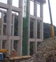
The retaining works in this bid section mainly include shoulder protection wall, toe protection wall, balance weight shoulder wall, balance weight embankment wall and cutting wall, with a total of 2113m and an average wall height of 2-13m.
Before the pouring of the next layer of concrete, clean it with clean water, and then pour the next layer of concrete The content of soil and rubble shall not be greater than 25%.
3 scope of application this scheme is applicable to an average height of not less than 6m and an area of not less than 1200m ² 4 project overview 4.1 Project Overview…
2 preparation principles: (1) monitor in strict accordance with the requirements of construction specifications and quality assessment and acceptance standards to ensure the construction quality of each subdivisional project; (2) strictly abide by the requirements of relevant national laws and regulations to ensure that no major safety accidents occur during construction and complete the safety management objectives; (3) Reasonably arrange the allocation of relevant data, construct in strict accordance with the process requirements and ensure the completion of the construction period goal on time; (4) do a good job in environmental protection, water and soil conservation and surrounding cultural relics protection in accordance with the requirements of relevant national laws and regulations; (5) reasonably arrange the site according to the standardization guidelines of XX Expressway to ensure that the construction site meets the requirements of civilized construction; (6) Establish and improve the temporary drainage system during construction.
(7) The starting end of the retaining wall is connected with the filling slope, and the cone slope is provided with M7.5 mortar rubble protection.
(4) C20 rubble concrete shall be preferentially used for the retaining wall according to the specific situation, and the mark number of rubble shall not be lower than mu30.
(6) the wall body of the submerged part along the river and weir pond shall be built with 15 rubble concrete.
(2) the part of the wall body above the ground line shall be provided with a drain hole every 2-3m, and the upper and lower walls shall be staggered.
4.1.2.2 technical standard for wall back backfilling (1) the internal friction angle of wall back backfilling material shall not be less than 35 °.
The holes shall be embedded Φ 5.59cm PVC pipe, the drain pipe shall be set with a slope of 3% – 4%, and the water outlet must be lower than the water inlet.
It shall be filled with sand gravel and wrapped with permeable geotextile.
4.1.1 brief description of retaining wall foundation works.
(3) after the foundation pit is excavated, the foundation shall be laid in time and backfilled and compacted.
The label of the embedded rubble shall be greater than 40 to ensure the bonding strength between the two layers of concrete.
(2) The lower part of the impervious geotextile of the retaining wall shall be backfilled with gravel, and the upper part shall be provided with a drainage layer with a layer thickness of not less than 30cm.
Before the final setting of the previous layer of concrete, rubble shall be embedded into the joint surface to form a convex tooth shape.
(3) When the amount of retaining wall concrete is too large, it can be poured in layers, and the layer thickness shall not be greater than 2.5m.
The drain pipe shall extend 10-20cm beyond the back of the structure, and its wall shall be set within 30cm Φ 1cm round hole shall be wrapped with permeable geotextile or connected with flexible permeable pipe.
(4) The maximum height HS of the expanded foundation shall be 2m, and it shall be set in a step shape and spread at 45 degrees.
(5) at the lower part of the lowest drainage hole of the retaining wall, the anti-seepage geotextile must be set within the excavation width of the foundation pit.
The permeable geotextile and permeable geotextile shall be 300g / m ² The long fiber non-woven geotextile and waterproof geotextile shall be 400g / m ² Waterproof geotextile..