After the camera is switched on, the subjective evaluation of image quality damage requires that there is no damage and interference on the image.
12.
2.
It is forbidden to install optical and cable joints in the Crossing Span crossing roads, railways or rivers when distributing panels.
There shall be no object blocking the monitoring target in the field of view of the lens.
According to the technical parameters provided by the face recognition system equipment supplier and the requirements of the engineering design drawings.
1、 The construction is based on Relevant specifications.
When erecting cameras near high-voltage live equipment, the safety distance should be determined according to the requirements of live equipment.
It is strictly prohibited to lay cables between the roofs of two buildings.
After laying, the optical cable shall be straight, without twist, excessive bending and mechanical damage.
7.
220V power line cannot be in the same pipe with weak current lines such as signal line and control line.
All cables entering the equipment or network box shall be treated with backwater bends to ensure that rainwater cannot enter the equipment or box along the cables.
The optical cable attenuation must meet the design requirements, mainly measuring the working attenuation of 1310nm and 1550nm windows, and paying attention to whether the outer sheath of the optical cable has cracks and fractures.
3.
The cable and power line of the camera shall be fixed, and the plug shall not be used to bear the dead weight of the cable.
10.
According to the technical parameters provided by the face recognition system equipment supplier, cooperate with the customer to make the reserved positions required for the installation of each equipment.
The outdoor network signal line must be of outdoor type.
specifications for cables.
The crystal head terminals at both ends of the network signal line adopt 568B standard (unless there are special requirements for individual equipment).
Obvious permanent labels shall be used at both ends of all network signal lines.
Cables should be laid along the wall in the lightning protection area, And shall not interfere with vehicle operation.
Standard 568B: orange white-1, orange-2, green white-3, blue-4, blue white-5, green-6, brown white-7, brown-8.
During the laying and installation of optical cables, the requirements of traction tension and radius of curvature shall be strictly controlled..
4.
2.
The camera lens should avoid strong direct light to ensure that the target surface of the camera tube is not damaged.
11.
The construction of the security protection system of the intelligent community is based on relevant national and industrial specifications and standards, The basis and requirements are as follows: Code for design of security engineering gb50348-2016 standard for design of intelligent buildings GB / t50314-2019 technical requirements for security video surveillance face recognition system GB / t31488-2015 technical requirements for real time intelligent analysis equipment for security surveillance video gbt30147-2013 code for electrical design of civil buildings JGJ / T16 code for acceptance of Engineering quality of intelligent buildings gb50339 Code for engineering design of generic cabling system for buildings and building complexes gb/t50311 safety engineering procedures and requirements ga/t75-94 technical requirements for video security monitoring system ga/t367 technical requirements for access control system ga/t394 technical requirements for information transmission, exchange and control of safety video monitoring networking system gb/t28181 II.
3.
IV.
3、 Camera installation specification 1.
4.
Let’s have a detailed understanding of this issue.
All cables should not be exposed during routing.
The cable routing should try to choose a position that can not be directly touched by people.
Outdoor all-weather protective cover is used in outdoor environment to ensure that it can be used in spring, summer, autumn and winter, cloudy, sunny, rainy and windy weather.
10.
6.
PVC pipe, steel pipe and bridge shall be waterproof at the outdoor interface.
The camera lens should aim at the monitoring target from the direction of light source, and backlight installation should be avoided; When backlight installation is required, the contrast of the monitoring area should be reduced.
Configure the power supply lines and network links of various equipment.
8.
System installation specification defines the installation positions of various equipment and cameras in the face recognition system according to the requirements of engineering design drawings or technical schemes, the equipment models and installation dimensions at each position, and the installation requirements are determined according to the product manual provided by the supplier.
All cables, trunking, grounding wires (grounding flat iron) and casings along the direction of the pole should be bound with galvanized iron wire, and the binding spacing should be 60-70.
Cable test standard: International iso/iec11801; American ansi/tia/eia-568a.
5.
5.
The connection mode between PTZ and PTZ decoder and camera shall be in strict accordance with the product manual of PTZ decoder.
The installation height should be 3-5M from the ground indoors and 5-10m from the ground outdoors.
8.
The cable from the camera should have a margin of 1m, which should not affect the rotation of the camera.
PVC pipes, steel pipes or bridge routing should be used according to the site environment.
When the cable is installed along the wall, PVC pipes with a diameter of less than 20mm can be fixed with wire clips, and the spacing of wire clips should be controlled at about 60cm; Expansion screws should be used for fixing PVC pipes with a diameter of more than 40mm and all steel pipes and bridges, and the spacing of expansion screws should be controlled at about 100cm.
The camera in the elevator car should be installed on the top of the elevator car, at the opposite corner of the elevator operator, and should be able to monitor the panoramic view in the elevator car.
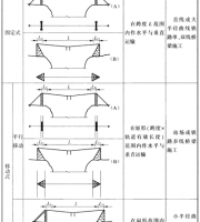
Construction process of face recognition and monitoring I Construction process cable laying → equipment installation → equipment commissioning → put into trial operation → completion data sorting → acceptance and delivery construction specification II.
9.
The camera shall be installed firmly and firmly.
After the camera is switched on, the automatic aperture adjustment function, focusing function, zoom function and other control functions should be normal.
1.
7.
The camera should be installed near the monitoring target where it is not vulnerable to external damage, and the installation location should not affect the operation of field equipment and normal activities of personnel.
9.
Before the optical cable is laid, the single disc test and distribution shall be carried out, and the A and B ends shall be laid according to the design requirements.
6.
The network signal line must adopt UTP cables that meet the standards above category 5.