2.1. Main specifications, regulations, and standards (timely updates of specification versions).
4.5.13. Relationship between external frame and unloading platform, external elevator, and tower crane attachment arm.
5.2.7. Typhoon prevention measures (this measure is required in areas with typhoons, and typhoon factors are considered in the design of the outer frame).
7.1.2. Sampling inspection number and quality judgment standards for fastener tightening.
7.1.3. Permissible deviations and inspection methods for scaffolding installation.
8.2.1. Emergency measures for falling from heights during high-altitude operations:.
8.2.2. Emergency measures for electric shock accidents caused by maintenance of electrical appliances, use of electric machinery, tools, etc.
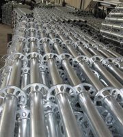
The above ground outer frame of this project adopts a floor standing steel pipe scaffold as a structural scaffold, external wall masonry and plastering operation frame. During the decoration phase, the outer frame will be removed and the construction of soil materials will be completed using a suspended basket frame. The vertical distance of the scaffold upright is XXm, the horizontal distance is XXm (the horizontal distance should not exceed 1.05m), and the step distance is XXm (the step distance should not exceed 1.8m). The specific form of scaffold selection is shown in the table below:.
(1) When the scaffold foundation is undisturbed soil or backfill soil, it should be specified whether it is undisturbed soil or backfill soil, as well as the bearing capacity value..
When setting up a ground scaffold on the backfill soil, a 2:8 lime soil is used for layered compaction of the backfill soil, with a compaction coefficient that meets the design requirements. The compactness is tested using a ring knife sampling method, and a 100 thick C15 cushion layer is poured on the layered compacted backfill soil as the supporting layer for the upright pole..
(2) If the scaffold foundation is a floor slab, the general situation of the floor slab, the bearing capacity value, whether it needs to be jacked back, and the number of layers of jacked back shall be stated..
When setting up a floor scaffold on the roof of the garage structure, the formwork of the basement roof in this area must wait for the concrete of the basement roof to reach 100% of the design strength before it can be removed. Formwork that has not reached the concrete design strength on the top plate of the basement shall not be removed, and the formwork shall serve as the top support for the upper landing scaffold..
(Reminder: The design of the external frame installation plan should fully consider factors such as outdoor elevator installation, unloading platform, secondary structure masonry of the exterior walls on each floor above ground, installation of external curtain walls, and installation of steel structures.).
(1) The scaffolding of Building 1 is erected at a height of XXm, with a vertical distance of XXm and a horizontal distance of XXm. The step distance is XXm, and the distance between the inner row of vertical poles and the structure is XXm. The height of the double vertical poles at the bottom is XXm, and the connecting wall components are set according to X steps and X spans;.
(2) The scaffolding of Building 1 is erected at a height of XXm, with a vertical distance of XXm and a horizontal distance of XXm. The step distance is XXm, and the distance between the inner row of vertical poles and the structure is XXm. The height of the double vertical poles at the bottom is XXm, and the connecting wall components are set according to X steps and X spans;.
Leveling and tamping the site → positioning and setting up the upright tube base plate → discharging the longitudinal bottom tubes one by one → erecting the vertical bottom tubes and then fastening them to the longitudinal bottom tubes → installing the horizontal bottom tubes and fastening them to the upright tubes or the longitudinal bottom tubes → installing the first step of large cross bars and small cross bars → installing the second step of large cross bars and small cross bars → adding temporary diagonal braces, the third step of large cross bars and small cross bars → installing cross braces → installing wall fasteners → binding safety nets → laying scaffold boards and toe boards horizontally → binding body railings → erecting upward circularly.
Dismantle safety net → dismantle guardrail → dismantle scaffold board → dismantle large crossbar → dismantle small crossbar → dismantle diagonal brace → dismantle upright pole → transmit to the ground → remove fasteners → stack according to specifications → cycle upwards for dismantling.
(1) Landing Feet.


