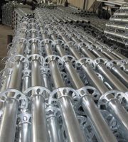
The cantilever scaffolding, with its advantages of simple structure, convenient operation, reduced investment in steel pipes, and saving labor costs, has won the favor of a large number of construction enterprises, and the higher the building, the more economical it is. During the implementation process, the “external scaffolding installation process” should be combined with civilized construction on the construction site to ensure that the facade of the external scaffolding is clean and beautiful, with prominent slogans and clear markings..
Process flow: construction preparation → laying out and positioning → pre embedding round steel anchor rings → installation of support structure for cantilever frame → vertical pole → fastening of longitudinal sweeping pole with vertical pole → installation of transverse sweeping pole → installation of longitudinal horizontal pole → installation of transverse horizontal pole → installation of connecting wall components → installation of scissor braces → tying of color strips and hanging of safety nets → laying of scaffolding and toe boards on the working layer..
The overhanging I-beams at the external corners of the structure intersect, and the length of the extending end cannot be guaranteed. If the length of the overhanging end is greater than 1.5, the I-beams on both sides are welded to the external corners at the intersection, with -200 × 200 × 10mm steel plates added on both sides. All contact points must be fully welded, and the height of the welding foot must not be less than 8mm, and there should be no air holes, slag inclusions, or missed welding..
The tail end of the cantilever beam should be fixed to the reinforced concrete beam slab structure at two or more locations. The diameter of the U-shaped steel reinforcement pull ring or anchor bolt of the anchored steel cantilever beam should not be less than 16mm (as shown in the figure below).
The length of the cantilever steel beam shall be determined according to the design, and the length of the fixed section shall not be less than 1.25 times the length of the cantilever section (except as specified). The fixed end of the steel cantilever beam should be fixed to the building structure beam and slab using two (pairs) or more “several” type steel reinforcement pull rings or anchor bolts. The “several” type anchor bolts should be embedded in the position of the bottom steel reinforcement of the concrete beam and slab, and should be welded or tied firmly with the bottom steel reinforcement of the concrete beam and slab. The anchorage length should comply with the provisions of the current national standard “Code for Design of Concrete Structures” GB50010 for steel reinforcement anchoring.
(1) Fixed distance positioning. Measure the distance between the inner and outer vertical poles and the wall at the four corners of the building using a ruler according to the construction requirements, and mark them properly; Straighten with a steel tape measure, mark the position of the upright pole, and mark the upright pole with a small bamboo piece; The cushion plate and base should be accurately placed on the positioning line, and the cushion plate must be laid flat without being suspended..
(1) During the process of setting up the first layer of scaffolding, a diagonal support is installed along each frame grid around the perimeter, and bi-directional support is added at the corners. The scaffolding can only be removed after it is reliably connected to the main structure’s connecting wall components. When the scaffolding operation level is two steps higher than the connecting wall components, it is advisable to first stand the outer row and then stand the inner row. The rest shall be erected according to the following structural requirements..
(2) The foundation of the scaffold should be compacted after backfilling, and hardened with concrete with a strength grade not lower than C15, with a hardening thickness of not less than 10cm. The bearing capacity of the foundation can meet the requirements for the installation of external scaffolding. The elevation of the upright pole pad or base surface is 50mm~100mm higher than the natural floor, and drainage ditches are set on both sides to ensure smooth drainage..
(3) The size of the cushion plate shall be made of wooden cushion plates or channel steel with a length of no less than 2 spans, a thickness of no less than 50mm, and a width of no less than 200mm..
(1) The upright pole is connected by butt joints, and the upright pole is connected to the longitudinal horizontal pole by right angle fasteners. The joint positions are arranged in a staggered manner, and two adjacent pole joints are avoided.


