3.5 Analysis of Key and Difficult Points in Engineering Construction and Corresponding Measures.
Based on the structural form of this project and considering the safety and reliability of the external scaffolding, the external scaffolding body of this project adopts a steel cantilever buckle type scaffolding. This plan is only for the construction and dismantling of steel cantilever scaffolding. For the construction of floor standing scaffolding, please refer to the “Construction Plan for Floor Standing Scaffolds” in this project..
Based on the external characteristics of the engineering building and combined with the actual situation on site, in order to facilitate earthwork backfilling construction, it is planned to start cantilever from the top plate of the first floor. The vertical distance of the frame upright is 1.5m, the horizontal distance is 0.9m, and the step distance is 1.5m. The tension node is two steps and two spans. The main beam of the cantilever I-beam is made of 18 # I-beam, and the connecting beam is made of 18 # I-beam. The external corners are reinforced..
Among them, there is no floor slab on the top of the fifth floor of the second cantilever on the north side of the 14-17/G-H axis. The steel cantilever outer frame in this section will start from the bottom plate of the fifth floor and be connected to the outer scaffolding of other sections to form a whole..
I-beam blanking, roof template snapping, anchor ring positioning → embedded reinforcement anchor ring → beam and slab concrete pouring completed and reached strength → I-beam is installed and fixed with the anchor ring, and I-beam is welded on the I-beam → laying operation scaffold board → installing the first step from the frame (upright, cross bar) → adding temporary diagonal brace, Tighten the upper end with the second step crossbar → Adjust the elevation of the upright pole and the levelness of the frame → Install the diagonal pole from the first step to the frame → Install the second step to the frame → Install the connecting rod to the wall → Install the third and fourth steps →… → Install the last step to the frame → Install the connecting rod to the wall → Add scissor braces → Lay the scaffold board → Bind the protective and foot blocking board, and hang a lightweight steel plate safety net for protection → Acceptance → Use..
Principle of dismantling: From top to bottom, it should be dismantled layer by layer and step by step; The process flow for dismantling each floor is as follows:.
Dismantle the guardrail → dismantle the scaffold board → dismantle the small crossbar → dismantle the large crossbar → dismantle the diagonal brace → dismantle the upright pole → transfer the upright pole to the ground → dismantle the connecting beam → dismantle the I-beam → remove the fasteners → stack according to the specifications → remove the materials from the site..
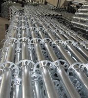
The cantilever scaffold of this project is erected using a socket type buckle scaffold, using 48 series buckles. The 18 # I-beam is used as the cantilever main beam, and the I-beam is arranged around the structure with a spacing of no more than 1500mm. The length of the fixed section of the I-beam is greater than or equal to 1.25 times the length of the cantilever section..
The outer lower part of the junction between the cantilever I-beam and the edge beam needs to be welded with a limit steel plate (200mm x 100mm x 10mm) on the I-beam. The limit steel plate should be placed vertically in the center and fully welded with the bottom surface of the I-beam. A 10mm thick triangular vertical reinforcement rib plate should be welded at the junction of the two to strengthen the connection. And use a 16mm diameter steel wire rope for tying, and embed it in the upper and upper beams through flower basket bolts Ф 20HPB300 round steel bar hanging ring tie, with 4 rope clamps at the end of the steel wire rope, with a spacing of 150-200mm between the rope clamps..
The fixed end of the 3-beam cantilever beam is fixed to the structural body using three U-shaped anchor bolts. The U-shaped bolts are embedded in the position of the steel bars at the bottom of the concrete beam and slab, and tied firmly with the steel bars at the bottom of the concrete beam and slab..
The anchoring floor slab should be pre equipped with load-bearing steel bars to withstand the negative bending moment caused by the anchoring end of the cantilever beam. Otherwise, support and unloading measures should be taken;.
On cantilever floor beams and slabs.


