① Dig a mud pit, which is 2.0m long, 1.2m wide and 1.0m deep according to the site conditions.
8 lines are shared above the frame bridge (from east to west, they are: track 3, track I, track II, platform 2, track 4, track 6, track 7, cargo platform, track 8 and track 9.
Fill the filter material with filling material.
If the immersed pipe is not sinking, the concrete retaining wall can be poured manually.
In this way, we can see the geology and water level intuitively.
The railway shall be bound firmly, wrapped with glass fiber cloth.
It is sunk with excavation.
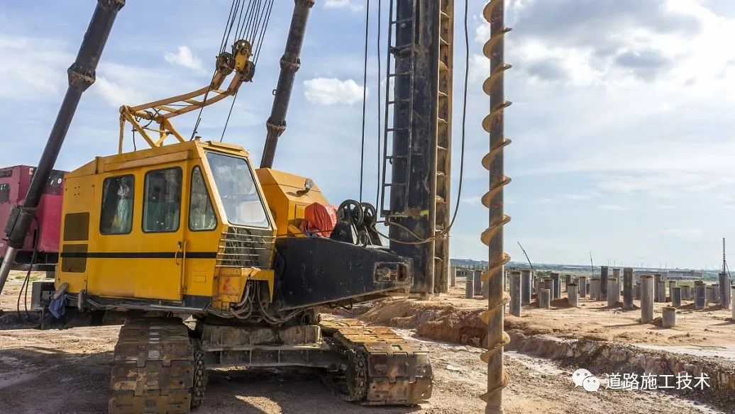
Scheme 1: manual excavation of hole digging pile; scheme 2: small drilling rig drilling.
An iron pipe with a diameter of 32mm shall be installed around the immersed pipe, and uneven holes shall be arranged on the iron pipe.
The construction is carried out with small drilling rig, and the depth of dewatering well cannot meet the design requirements.
The first jacking section is located below the line 3, I and II, and the second jacking section is located on the line 4, 6 and 7.
The well hole should be kept round and vertical.
If the sinking pipe does not sink, inject white mud into the iron pipe with high-pressure mud pump as lubricant.
One skylight point is planned to be excavated for 1m)..
Due to the poor site geological conditions, the construction method of hole digging pile needs to test one pile in the section outside the line that does not affect the driving and ensure the safety of the line.
Small assembled drilling (see attached figure) combined with comprehensive factors, ① according to the design drawing, the pebble layer with geological conditions below 10m is found.
When the filling amount is not consistent with the theoretical calculation, find out the cause in time.
The shovel will be used to prevent uneven or impact on the shaft lining.
The cast-in-situ section I is located in the southeast of the jacking section I, under the railway fence and the undisturbed path, the cast-in-situ section II is located under the track 8 and 9, and the cast-in-situ section III is located in the northwest of the cast-in-situ section II, which is located outside the earth platform and the original path outside the station.
1、 Project Overview: the jacking frame bridge is located at k593 + 082 of * * railway station and is set for interchange.
The PVC pipe joint shall be glued, and then the hole shall be drilled on the pipe.
Two roofs are adopted The construction of the incoming section and 3 cast-in-situ sections shall be completed.
According to the design requirements, the depth of the dewatering well is about 16m, so the dewatering effect cannot be achieved.
⑧ After the networking of precipitation, the water pump shall be started effectively and reasonably according to the change of water level.
Excavate layer by layer from top to bottom with pick and shovel, and break it with hammer and drill in case of hard soil or gravel.
Manual hole digging between lines, in case of collapse in the hole, it will endanger the driving safety.
⑤ After the well is washed and completed, the restorative pumping and washing shall be carried out repeatedly with the sewage pump, and the pumping and washing times shall not be less than 4 times.
The height of the drilling rig is 1.5-2m.
Among them, there are 6 protective piles in the range of 2 platforms φ 1.25m hole digging pile, 11m long, with 1.25m crown beam on the top of the pile.
Scheme 1: manual excavation shall be adopted, and the retaining wall shall be supported by immersed pipe or concrete.
The drilling diameter is not less than 200-300mm.
Construction method of dewatering well: manual small drilling tools are used for dewatering within the line, and the diameter of the lower part is 200pvc pipe.
⑦ The water pump is installed, the submersible pump is insulated and powered on, the cable and switch box are laid, and the leakage protection system is installed.
1.
Small drilling rig is used for drilling.
The foundation pit of the first jacking section is set in the southeast of the railway, and the foundation pit of the second jacking section is set in the northwest of the railway.
Each 1-5 wells share a mud pit.
Can not achieve the effect of precipitation.
The track type of track I and track II is 60kg / m, and the rest are 50kg / M; platform 2 is 8m wide and 30cm high; freight platform is 10m wide and 85CM high; earth platform is 70cm high.
This frame bridge is a 9m-9m double hole frame bridge underpass bridge, 109.313m long and 20.3m wide.
Sink with immersed pipe.
The form of hole digging pile is immersed pipe pile with a wall thickness of 10cm and a height of 0.5m.
④ The PVC pipe shall be used for hoisting and placing the PVC pipe.
2.
During the construction of frame bridge, 8 and 9 lines and cargo platforms are out of service.
2、 Construction scheme of hole digging pile before the excavation of hole digging pile, the dewatering construction shall be carried out within the scope of hole digging pile, and the dewatering well shall be adopted.
C25 reinforced concrete is adopted for the pile body.
The excavated pile shall be excavated according to the design pile diameter plus 10cm to control the section size.
The well pipe shall be 200mm higher than the ground, and the wellhead shall be covered.
Two construction schemes are planned.
Fill the height with the filter material.
24m and 12m combined D-Beam frame is adopted for empty reinforcement.
A total of 54 hole digging piles are required for line reinforcement, of which 24 piles are shared between the two lines φ The 1.5m hole digging pile is 11m long, and the pile top is a 1.25m crown beam.
It is installed at the wellhead and operated manually.
After well washing, if the filter material sinks too much, it shall be filled to 1m below the wellhead and sealed with clay.
The formation makes its own mud wall.
③ For the excavation of supporting piles between lines, there are 24 piles in total, 264 linear meters.
⑥ The outer layer of the well pipe filled with filter material is wrapped with double-layer filter screen, with a mesh of 3mm × 3m。 Fill the filter material immediately after the well casing is run in.
The excavation sequence is to excavate the middle first and then both sides.
② Excavate the debris in the upper part of the dewatering well, pour the upper mud retaining wall, and construct by manual excavation.
③ The construction of the drilling dewatering well adopts the positive circulation drilling rig to form the hole.
Scheme 2: if the test pile encounters quicksand during excavation, and the depth of the dewatering well can not meet the design requirements, and the dewatering well can not achieve the dewatering effect, the small assembled drilling rig shall be used for construction.
The PVC pipe shall be divided into sections.
In case of pebble layer during drilling construction, the depth of dewatering well can only be more than 10m.
No loader direct filler should be used.
66 skylight points are planned (8 groups, 6 people in each group, including 4 people dumping soil.
② Limited by the site topography, the distance between lines is 5m, so it is difficult to construct manually.
The soil excavated in the hole is loaded into a bucket, erected a tripod, lifted by a wooden winch, transported vertically to the ground and bagged to the outside of the subgrade.
The jacking of frame bridge strengthens 3, I, II, 4, 6 and 7 lines.
The filter material shall be filled evenly around the well bore, which shall be kept continuous, and the mud shall be squeezed out of the well bore.
Manual excavation of hole digging piles requires excavation in skylight points and blocking points.