Source: the copyright of Zhulong forum belongs to the original author
. 
This specification refers to the technical code for safety of fastener type steel pipe scaffold in building construction (jgj130-2011)
. 
1、 Preparation for erection 1.1 construction scheme and disclosure: safety technical disclosure shall be made to scaffolders before scaffold erection
. 
(see specification 7.1.1) 1.2 scaffold erection and dismantling personnel must be professional scaffolders who have passed the training and examination of government departments and issued legal certificates, and take up their posts with certificates after passing the regular physical examination
. 
1.3 scaffold erection personnel must wear safety helmet, protective glasses, reflective vest, labor protection shoes and safety belt
. 
1.4 the components and fittings that have passed the inspection shall be classified according to the varieties and specifications, stacked neatly and stably, and there shall be no ponding in the stacking site
. 
(see specification 7.1.3) 1.5 the debris on the erection site shall be removed, the erection site shall be leveled, and the drainage shall be smooth
. 
(see specification 7.1.5) 1.6 after the scaffold foundation passes the acceptance, it shall be set out and positioned according to the requirements of construction organization design or special scheme
. 
(see specification 7.2.4) II
. 
Vertical pole 2.1 the elevation of base plate or base bottom of vertical pole should be 50 mm ~ 100 mm higher than natural floor, and the base plate should be wood base plate with length of no less than 2 spans, thickness of no less than 50 mm and width of no less than 200 mm
. 
(see specification 6.3.1) (see specification 7.2.3) 2.2 scaffolds must be equipped with vertical and horizontal sweeping poles
. 
The longitudinal sweeping pole shall be fixed on the vertical pole not more than 200 mm away from the bottom of the steel pipe with right angle fasteners
. 
The horizontal sweeping pole shall be fixed on the vertical pole close to the bottom of the longitudinal sweeping pole with right angle fastener
. 
(see specification 6.3.2) 2.3 when the vertical pole foundation of scaffold is not at the same height, the vertical sweeping pole at the high place must be extended to the low place for two spans and fixed with the vertical pole, and the height difference shall not be greater than 1m
.
The distance between the axis of the vertical pole above the slope and the slope shall not be less than 500mm (see 6.3.3 of the specification)
.
2.4 except for the top step of the top layer, the joints of other layers must be connected by butt fasteners
.
The butt fastener of the vertical pole shall be staggered, the joints of two adjacent vertical poles shall not be set in the synchronization, and the staggered distance of the two separated joints separated from a vertical pole in the height direction shall not be less than 500 mm; the distance between the center of each joint and the main node shall not be greater than 1 / 3 of the step distance; (see 6.3.6) 2.5 when the vertical pole adopts the lap length, the lap length shall not be less than 1 m, and the lap length shall be less than 1 m No less than 2 rotating fasteners shall be used for fixation
.
The distance between the edge of the end fastener cover plate and the rod end shall not be less than 100 mm
.
(see specification 6.3.6) III
.
longitudinal horizontal bar 3.1 longitudinal horizontal bar shall be set at the inner side of vertical bar, and the length of single bar shall not be less than 3 spans; (see specification 6.2.1) 3.2 longitudinal horizontal bar extension shall adopt butt joint or lap joint, and the joint of two adjacent longitudinal horizontal bars shall not be set in synchronous or same span; the staggered distance of two adjacent joints in horizontal direction of asynchronous or different spans shall not be less than 500mm The distance between the center of each joint and the nearest main node shall not be greater than 1 / 3 of the longitudinal distance (see 6.2.1 of the specification)
.
3.3 the lap length of longitudinal horizontal members shall not be less than 1m, and three rotating fasteners shall be set at equal intervals for fixation
.
The distance between the edge of the fastener cover plate at the lap end and the end of the lap longitudinal horizontal bar shall not be less than 100 mm (see 6.2.1 of the specification)
.
3.4 when stamping steel scaffold board, wood scaffold board and bamboo strand foot are used For the scaffold board, the longitudinal horizontal bar shall be used as the support of the transverse horizontal bar, and fixed on the vertical bar with right angle fasteners
.
Both ends of the transverse horizontal bar of the double row scaffold shall be fixed on the longitudinal horizontal bar with right angle fasteners (see 6.2.1 of the specification)
.
IV
.
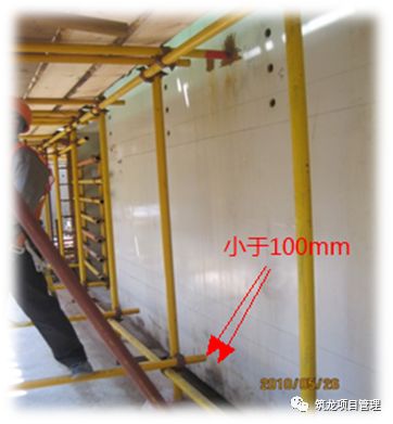
the transverse horizontal bar at the non main node on the operation layer of the transverse horizontal bar 4.1 shall be set at equal intervals according to the needs of supporting the scaffold board, and the maximum spacing shall not be less than 0 It shall be greater than 1 / 2 of the longitudinal distance; (see specification 6.2.2) 4.2 the distance between the end of the horizontal bar against the wall and the decorative surface of the wall shall not be greater than 100 mm; (see specification 7.3.6) 4.3 a horizontal bar must be set at the main node, which shall be connected with right angle fasteners and shall not be removed
.
(see specification 6.2.3) v
.
scaffold board 5.1 scaffold board of operation layer shall be fully, stably and solidly paved; (see specification 6.2.4) 5.2 stamping steel scaffold board, wood scaffold board and bamboo strand scaffold board shall be set on three horizontal bars
.
When the length of the scaffold board is less than 2m, it can be supported by two horizontal bars
.
However, both ends of the scaffold board should be reliably fixed with the horizontal bar to prevent overturning
.
The probe length should be 150 mm
.
(see specification 6.2.4) 5.3 the scaffold board shall be laid by butt or lap
.
When the scaffold board is butt laid, two horizontal bars shall be set at the joint, the overhanging length of the scaffold board shall be 130mm ~ 150mm, and the sum of the overhanging length of the two scaffold boards shall not be greater than 300mm; when the scaffold board is overlapped, the joint shall be supported on the horizontal bar, the overlapping length shall not be less than 200mm, and the length of the overhanging horizontal bar shall not be less than 100mm
.
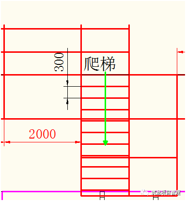
(see 6.2.4 of the code) 6.1 the wall connecting parts shall be set close to the main node and steel connection, and the distance away from the main node shall not be more than 300 mm (see 6.4.3 of the code)
.
6.2 the wall connecting parts shall be set from the first longitudinal horizontal bar of the bottom layer
.
When it is difficult to set at this place, other reliable measures shall be adopted to fix them (see 6.4.3 of the code)
.
6.3 the wall connecting parts shall be preferentially arranged in diamond shape, or adopt the steel connection Square and rectangular layout (see 6.4.3) 6.4 both ends of open scaffold must be equipped with wall connecting pieces, and the vertical spacing of wall connecting pieces shall not be greater than the floor height of the building, and shall not be greater than 4m
.
The wall connecting rod in the wall connecting parts shall be set horizontally
.
When it cannot be set horizontally, it shall be connected downward to one end of the scaffold
.
(see 6.4.5 of the specification) 6.5 when the scaffold starts to be erected or the lower part of the scaffold can not be provided with wall connecting parts temporarily, the throwing support shall be set up with 6 spans apart
.
The throwing support shall be fixed on the scaffold with full-length rods and rotating fasteners
.
The inclination angle with the ground shall be between 45 ° and 60 ° and the distance from the center of the connection point to the main node shall not be greater than 300 mm
.
The throwing support shall be removed after the wall connecting parts are erected
.
(see specification 6.4.7) 6.6 the double row scaffold must be erected in accordance with the construction progress, and the erection height at one time shall not exceed two steps above the adjacent wall connecting parts; if it exceeds two steps above the adjacent wall connecting parts, and it is impossible to set the wall connecting parts, measures such as bracing and fixing shall be taken to tie up with the building structure
.
(see specification 7.3.1) VII
.
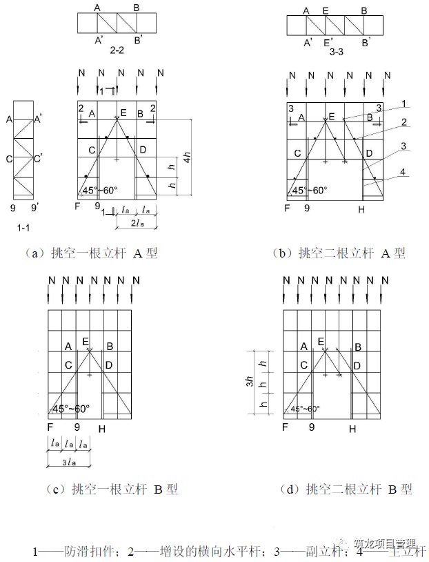
Door opening 7.1 single row and double row scaffold door openings should adopt rising inclined bar and parallel chord truss structure (as shown in the figure below)
.
The inclination angle a between the inclined rod and the ground should be between 450 and 600
.
The type of door opening truss should be determined according to the following requirements: when the step distance (H) is less than the longitudinal distance (LA), type A should be adopted; when the step distance (H) is greater than the longitudinal distance (LA), type B should be adopted, and should meet the following requirements: 1) when h = 1.8m, the longitudinal distance should not be greater than 1.5m; 2) when h = 2.0m, the longitudinal distance should not be greater than 1.2m
.
(see specification 6.5.1) 7.2 for the space truss at the door opening of double row scaffold, except for the lower chord plane, a diagonal web member (section 1-1, 2-2 and 3-3 in the figure) shall be set between the nodes in the other five planes
.
The diagonal web member shall be fixed on the extended end of the transverse horizontal bar intersected with it by rotary fastener, and the distance between the center line of the rotary fastener and the main node shall not be greater than 150 mm
.
(see specification 6.5.2) 7.3 when the diagonal web member crosses two steps in one span (figure a type), a transverse horizontal bar should be added at the intersecting longitudinal horizontal bar to fix the diagonal web member on its extended end.
.