1、 Foreword (1) the erection and construction management of fastener type steel pipe external scaffold for building construction reflects the enterprise’s characteristic external scaffold image and standardized construction ability
. 
This standard compiles the internal standard for erection of external scaffold for building engineering in accordance with relevant national and local safety technical specifications
. 
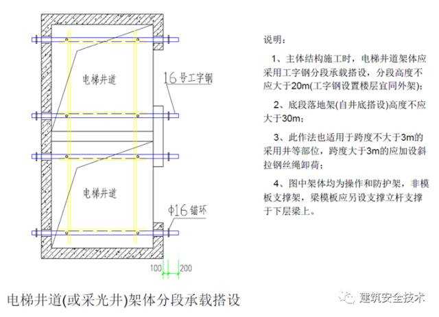
(2) This standard specifically states the facade image, structural requirements, erection and demolition, inspection and acceptance, and management requirements of external scaffolds, and details the structural methods of some special parts, including balcony, bay window, external elevator unloading platform, elevator shaft and lighting shaft, building external corner, etc
. 
(3) If the specific contents of this standard do not conform to the requirements of relevant national and local safety technical specifications, the relevant national and local safety technical specifications shall prevail
. 
2、 Basic parameter requirements (1) steel pipe material requirements: steel pipe shall be Q235 ordinary steel pipe specified in national standard GB / t13793 or GB / t3091, and the model shall be Φ 48.3 × 3.6mm (the scheme is calculated according to Φ 48 × 3.0mm)
. 
The material shall be provided with product certificate and accepted before being put into use
. 
(2) When the fastener enters the construction site, the product certificate shall be inspected, and the sampling retest shall be conducted
. 
The technical performance shall meet the provisions of the national standard “steel pipe scaffold fastener”
. 
The appearance inspection of the fastener shall be free of cracks, and the bolt shall not be damaged when the tightening torque reaches 65N · M
. 
(3) The steel pipe of the outer scaffold must be antirust treated, and one layer of antirust paint and two layers of finish paint shall be applied after derusting
. 
(4) The model of wooden scaffold board is 3000 (6000) × 200 (250) × 50, and both ends are bound with Φ 1.6 mm galvanized iron wire; the steel mesh scaffold is made of hpb235 Φ 6 steel bar, with a cross section of 40 mm, and fixed on the small cross bar with Φ 1.6 mm galvanized iron wire
. 
3 steel pipe color (1) yellow paint: scaffold pole, big and small cross bar, vertical and horizontal sweeping pole
. 
(2) Red paint: wall attachment
. 
(3) Yellow and black two-color paint: external protective railings of scaffold, ramp protective railings and unloading platform protective railings
. 
(4) Red and white two-color paint: cross bracing, horizontal diagonal bracing, skirting board, stair edge guard rail, construction elevator unloading platform edge guard rail
. 
(5) If the color of the schematic diagram is inconsistent with that of the text description, the color of the text description shall prevail
. 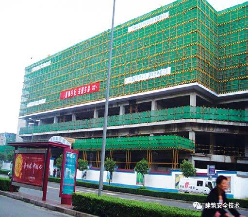
(1) the external protection of scaffold must be closed with qualified dense mesh safety net
. 
The company logo (“company” banner) and slogan shall be set on the outer shelf
. 
Ensure the coordination and beauty of the external shelf, and reflect the characteristics of the enterprise
. 
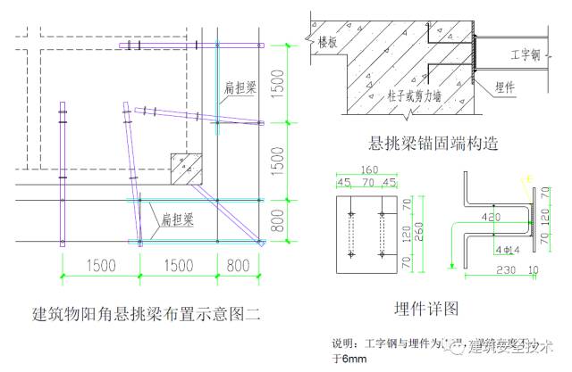
(1) four vertical poles shall be set at the internal and external corners of the scaffold body, and the large cross bar shall be connected and closed
. 
(2) Horizontal bar must be set at the main node
. 
(3) Except the top of the top layer, the vertical pole must be butted, the large cross bar can be overlapped outside the frame corner, and the cross bracing must be overlapped
. 
(4) The cross bracing and wall connecting parts must be erected and removed simultaneously with the external scaffold
. 
It is forbidden to build later or dismantle first
. 
6
.
Pole foundation (1) the height of floor type scaffold should not exceed 35m
.
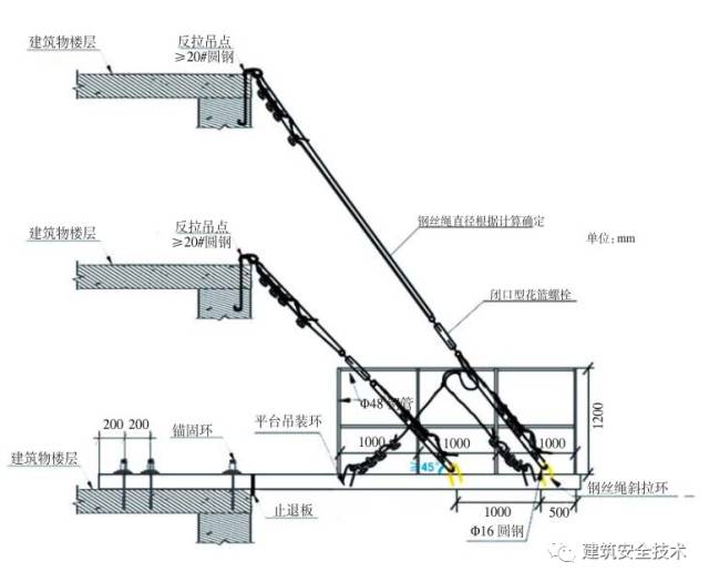
Unloading measures must be taken when the height is between 35m and 50m, and unloading measures must be taken when the height is more than 50m
.
The special scheme shall be demonstrated by experts
.
(2) The scaffold foundation shall be flat, compacted and hardened with concrete
.
The foundation shall be hardened with 100 mm thick C25 concrete, and the base or base plate shall be set at the bottom of the vertical pole
.
The base plate shall be made of wood with a length of not less than 2 spans, a thickness of not less than 50 mm and a width of not less than 200 mm
.
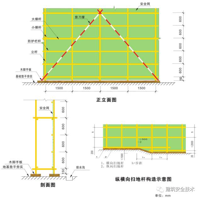
(3) Floor type scaffold must be equipped with vertical and horizontal sweeping poles
.
The vertical sweeping pole should be fixed on the vertical pole close to the vertical sweeping pole with direct fasteners
.
When the vertical pole foundation is not at the same height, the vertical sweeping pole at the high place must be extended to the low place for two spans and fixed with the vertical pole
.
The height difference shall not be more than 1m, and the distance between the vertical pole axis and the slope above the slope shall not be less than 500mm
.
(4) Drainage measures shall be set around the scaffold foundation
.
The bottom elevation of the scaffold base shall be 50 mm higher than the outdoor natural floor
.
A drainage ditch with a section of not less than 200 mm × 200 mm shall be set outside the pole foundation to ensure that there is no ponding in the scaffold foundation
.
Scaffold foundation drainage ditch drawing ■ scaffold foundation section drawing ■ steel base schematic diagram 7 elevation protection (1) dense mesh safety net shall be hung on the outside of the scaffold, with mesh number no less than 2000 mesh / 100cm2
.
Mesh connection shall be adopted when the net body is vertically connected, and each mesh shall be fixed with 16 # iron wire and steel pipe
.
Overlapping method shall be adopted when the net body is horizontally connected, and the overlapping length shall not be less than 200 mm
.
Wood brace should be set as inner lining at the corner of the frame to ensure the beauty of the safety net at the corner of the frame
.
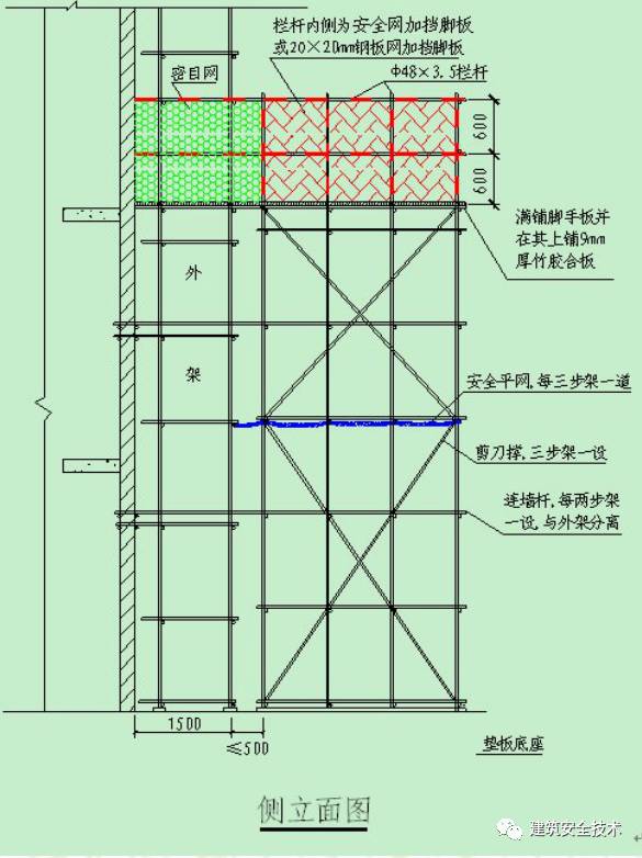
(2) 180mm toe board is set at the bottom of the scaffold from the second step, and a protective railing of the same material is set at the height of 600mm and 1200mm respectively
.
If the inner side of the scaffold forms the edge, the outer side of the scaffold shall be protected
.
(3) Yellow paint shall be applied on the surface of the outer row of vertical poles and large cross bars of the scaffold, and yellow and black paint shall be applied on the surface of the waist bar
.
A 200 mm high warning tape shall be set on the outer side of the vertical pole every 3 layers or 9 M
.
The size of warning tape is shown in the figure, and the surface is painted with red and white warning color
.
(1) the operation layer must be fully paved with scaffold board, and the distance between scaffold board and building structure shall not be more than 150 mm
.
(2) The second floor of the landing frame, the first floor of the cantilever frame (climbing frame), and the middle layer of not more than 10m and not more than three layers are fully paved with a hard partition protection
.
The horizontal pocket net must be hung to the building structure in the middle of the two layers of hard protection
.
(3) The clear distance between the inner upright pole and the scaffold body is generally not more than 200 mm
.
If it is more than 200 mm, a flat and firm standing piece must be laid
.
When the gap between the scaffold board on the working floor and the building is more than 150 mm, it should be fully closed to prevent personnel and materials from falling
.
9 wall connecting parts (1) the surface of wall connecting parts shall be painted with red eye-catching paint to facilitate inspection and warning
.
(2) The scaffold must adopt rigid wall connecting parts
.
(3) The wall connecting parts should be set from the first longitudinal horizontal bar of the bottom layer
.
When it is difficult, reliable measures should be taken to fix them
.
The wall connecting parts should be arranged in diamond shape, square shape and rectangle shape
.
(4) The wall connecting parts shall be set close to the main node, and the distance away from the main node shall not be greater than 300 mm (5) the spacing of the wall connecting parts shall be in accordance with the design calculation provisions, and shall comply with the provisions of “maximum spacing of the wall connecting parts arrangement” in the following table
.
(6) Both ends of the straight and open scaffolds must be equipped with wall connecting pieces, and the vertical spacing of the wall connecting pieces shall not be greater than the floor height of the building, and shall not be greater than 4m (two steps)
.
10 cross bracing and horizontal diagonal bracing (1) cross bracing shall be set continuously from bottom to top from the bottom corner of scaffold, and the surface of cross bracing shall be painted with red and white warning color
.
(2) The number of vertical poles crossed by each cross brace shall be determined according to the following table
.
The width of each cross bracing should not be less than 4 spans, and should not be less than 6 meters
.
The inclined angle between the diagonal bar and the ground should be 45 ° to 60 ° and 45 ° to 60 ° respectively
.
(3) For the floor type outer frame less than 24 meters, vertical continuous cross bracing shall be set at the two ends of the outer side of the frame, the corner and the elevation with an interval of no more than 15 meters in the middle
.
For the floor type outer frame and all cantilever frames above 24 meters, continuous cross bracing shall be set up on the whole facade outside the frame
.
(4) The length of scissor strut should be overlapped, the length of overlapping should not be less than 1m, and not less than 3 fasteners.
.