Source: the copyright of Xiamen Construction Bureau belongs to the original author 1
. 
Management requirements 1
. 
Scaffold engineering in this atlas refers to floor type steel pipe scaffold and section steel cantilever type steel pipe scaffold, which are respectively composed of frame foundation, frame structure, frame protection and ramp
. 
The erection and dismantling of scaffold works shall be in accordance with the current “Regulations on safety management of divisional and subdivisional works with greater risks”, order No
. 
37 of the Ministry of housing and construction, unified standard for safety technology of construction scaffold (gb51210-2016), technical code for safety of steel tubular scaffold with couplers in construction (jgj130-2011), and “Regulations on safety management of divisional and subdivisional works with greater risks” According to the relevant regulations and standards, such as the notice on Relevant Issues of the Ministry of construction, Jian ban Zhi [2018] No
. 
31, the notice on strengthening the safety control of major hazard installations in construction (min Jian Jian [2017] No
. 
30), etc
. 
2
. 
Before scaffold construction, a special construction scheme shall be prepared
. 
The scaffold body shall be provided with design calculation sheet, detailed structural drawing of main nodes, plane drawing of scaffold body, section drawing, etc., which shall be reviewed and approved by the technical director and chief supervision engineer of the construction enterprise
. 
Full time safety management personnel must be present during the installation and removal process
. 
The floor type steel pipe scaffold with height of 50m and above and the special construction scheme of section steel cantilever steel pipe scaffold with height of 20m and above can be implemented only after expert argumentation
. 
3
. 
Scaffold erection personnel must hold the construction scaffolder operation certificate issued by the Ministry of housing and urban rural development, and within the validity period
. 
4
. 
Foundation is an important part of scaffold stability
. 
When the ground resistance and settlement of the foundation do not meet the specification requirements, it is strictly forbidden to set up floor type steel pipe scaffold, and the cantilever steel pipe scaffold can be preferred
. 
5
. 
The outside of scaffold shall be fully hung with dense mesh safety net with flame retardant performance meeting the requirements
. 
6
. 
The material specifications of scaffold bars, fasteners, etc
. 
shall meet the specification requirements and fire protection requirements
. 
It is strictly forbidden to mix two kinds of steel pipes with different diameters
. 
7
. 
The tightening torque of fastener bolt shall not be less than 40n · m and not more than 65N · M
. 
8
. 
The scaffold should be checked and accepted before use, and can be put into use only after passing the check and acceptance
. 
The daily inspection and maintenance work should be strengthened during use to ensure the safe use of the scaffold
.
9
.
At night, in case of gale above level 6 (including level 6), thunderstorm and other weather, scaffold erection and demolition are not allowed
.
2
.
Detail strengthening structure of scaffold 1
.
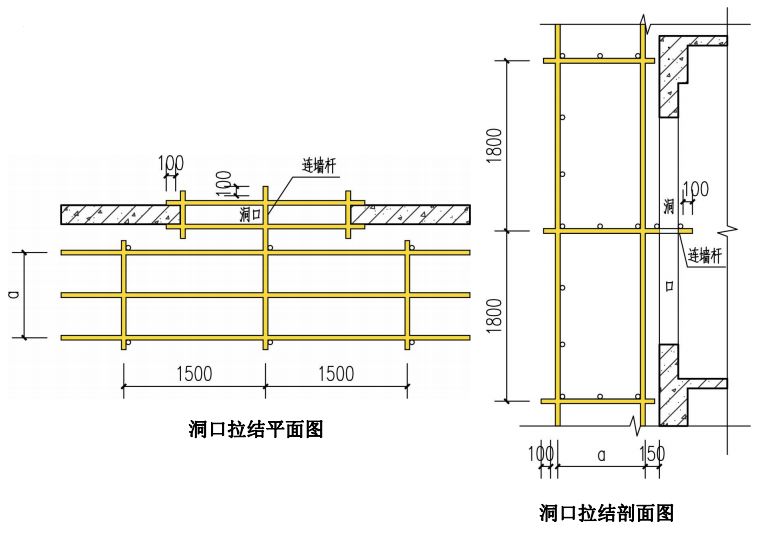
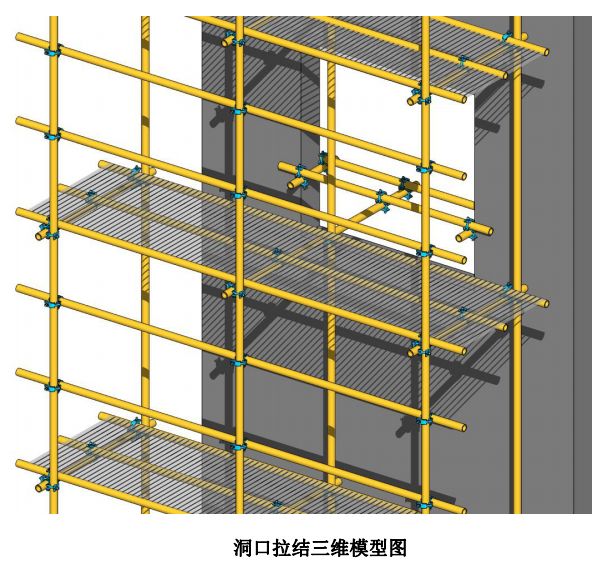
Details of hole connecting wall pulling structure: the extension of small cross bar of frame body is used as connecting wall rod, a is 800mm or 1050mm (800mm for cantilever scaffold and 1050mm for floor scaffold), and the exposed hole of connecting wall rod is ≥ 100mm
.
On the wall connecting rod, a steel pipe is attached to the inner and outer walls respectively, which is connected with fasteners
.
The exposed holes at both ends of the small cross bar are ≥ 100 mm
.
In the decoration stage, the wall needs to be added with finished product protection
.
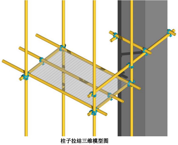
2
.
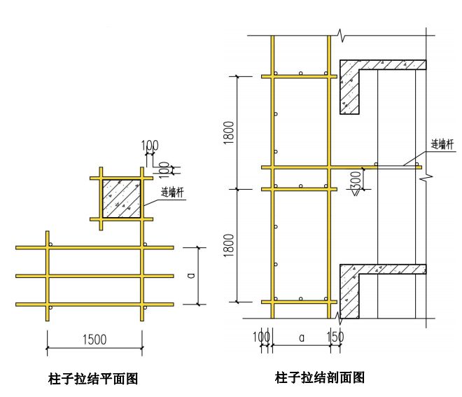
The method of connecting wall parts and holding column structure column tie details: when the connecting wall parts cannot be set in two steps and three spans at individual positions, the holding column reinforcement measures shall be adopted
.
A wall connecting rod is attached to the frame, which extends to one side of the column, and three small cross bars are attached to the other three sides of the column, which are connected with the wall connecting rod by fasteners to form an encircle
.
The exposed length of the steel pipe is more than or equal to 100mm3, and the structure of the cast-in-place brace is as follows: 1
.
This structure is used for buildings with large column spacing, storey height more than or equal to 5m, and the setting of the wall connecting parts can not meet the requirements of two steps and three spans
.
2
.
When setting up the throwing support, the throwing support is fixed on the scaffold with full-length rod and rotary fastener, and the inclination with the ground is 45 ° to 60 °
.
3
.
When the ordinary scaffold starts to set up a pole, it should also set up a throw brace every six spans, until the wall connecting pole is installed stably, it can be removed according to the situation
.
4
.
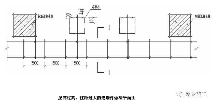
When the floor height is too high and the column spacing is too large, the lattice column can be added when the floor height is too high and the column spacing is too large
.
The section size of the lattice column should be 460mm × 460mm
.
The steel lattice is welded by four 150 mm × 150 mm × 12 mm angle steels and batten plates, and a steel pipe is set as the wall connecting member every two steps and three spans
.
When pouring the main body concrete, the embedded parts of lattice members should be set up
.
5
.
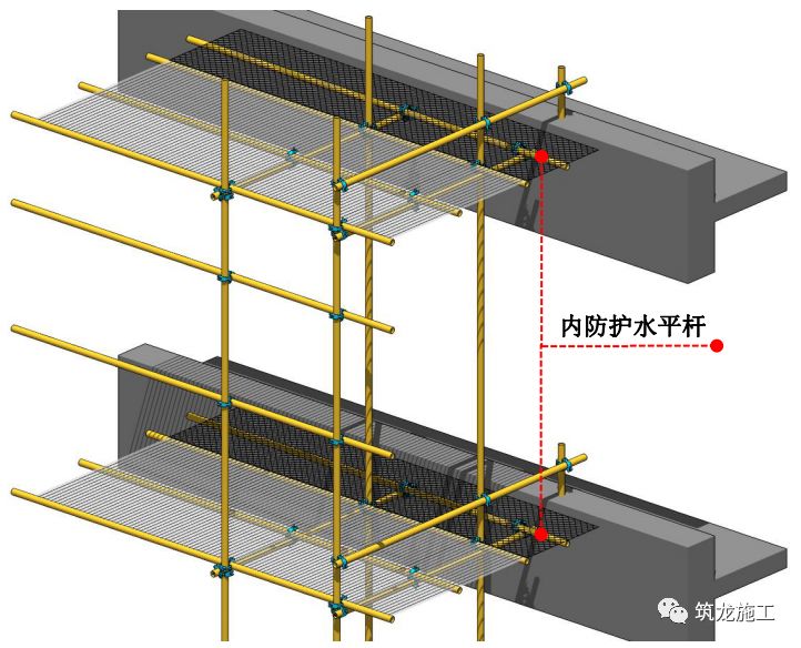
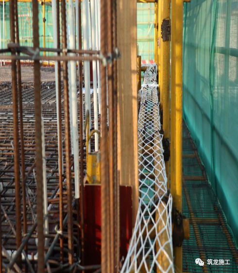
Details of outer frame inner protective structure outer frame core filling rod: the gap between the frame and the building should be less than 150 mm
.
When the gap is too large, the horizontal rod at the end close to the wall can be fully used for reasonable extension (it should not be greater than 40% of the frame width, and core filling rod should be added when it is greater than 400 mm)
.
The steel fence should be laid and safety devices should be hung on each layer The gap between the frame and the building can meet the requirements
.
1
.
Steel fence: when the gap between the frame and the building is greater than 400mm, the steel fence shall be used
.
2
.
Safety net: when the gap between the frame and the building is 150-400mm, the safety net should be used
.
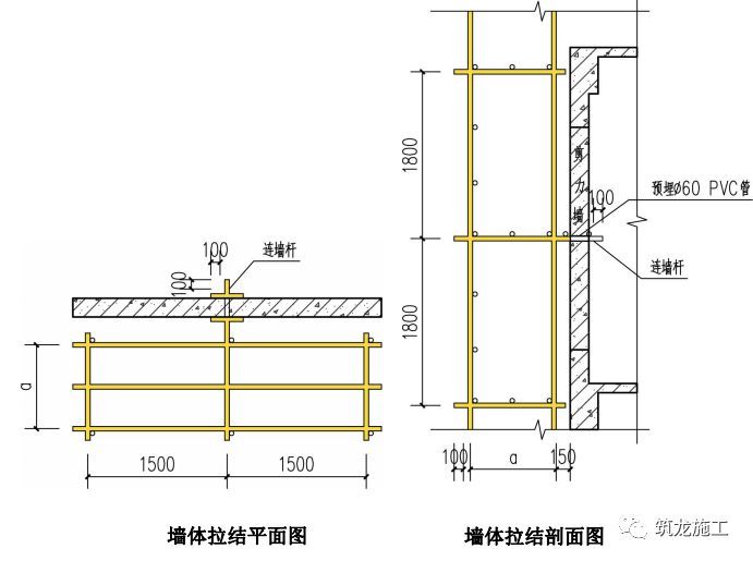
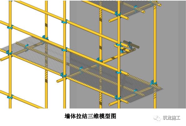
6
.
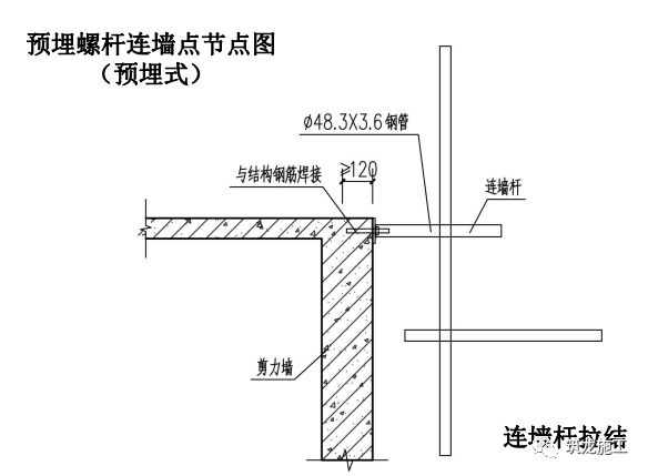
Construction of wall connecting parts at shear wall (method 1) details of wall tie: embed Φ 60mm PVC pipe in the shear wall, a is 800mm or 1050mm (800mm for cantilever scaffold and 1050mm for floor scaffold), and connect a wall connecting rod with the frame through the embedded pipe
.
On the wall connecting rod, a steel pipe is attached to the inner wall and the outer wall respectively, and the steel pipe is connected with a fastener
.
The exposed length of the small cross bar is not less than 100 mm
.
7
.
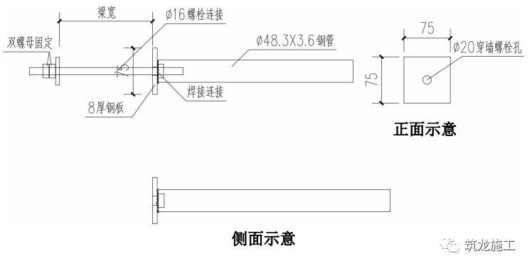
The structure of shear wall connecting parts (method 2) Description: 1
.
The outer frame connecting parts are divided into two types: embedded type and through wall type
.
2
.
Before concrete pouring, the embedded parts shall be embedded in the shear wall or beam (or through wall bolt hole shall be set), one end of the welding nut of the rigid connector shall be covered with the embedded parts (or through wall bolt), and the other end shall be fixed with the scaffold pole through the fastener
.
8
.
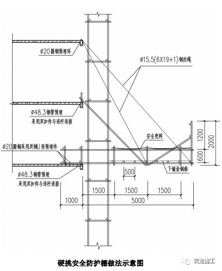
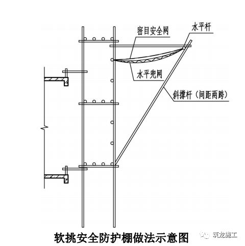
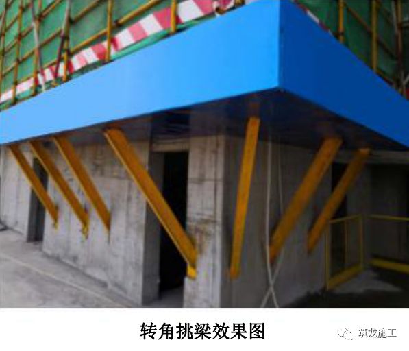
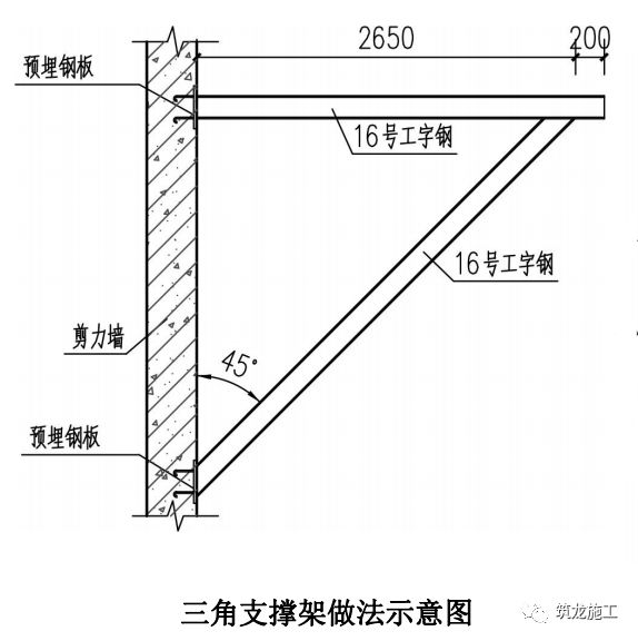
The horizontal protective structure of the outer frame (soft cantilever and hard cantilever) Description: 1
.
When setting up the soft cantilever, the full-length rod shall be used and the rotating fastener shall be used to connect with the scaffold The inclined angle between the inclined strut and the outer frame is 45 ° to 60 ° and one inclined strut is set for each two spans
.
Two protections are set at the top of the inclined strut to connect with the outer frame
.
The top and bottom of the inclined strut are dense mesh safety net and horizontal pocket net respectively
.
2
.
The specification of steel pipe not marked in the drawing is Ф 48.3 mm × 3.6 mm
.
The hard protective shed and the outer frame are independent, and shall not be connected by any rod
.
One cantilever steel pipe is set every 1.5m, the cantilever length is about 5m (it can be adjusted according to the actual situation of the project and through calculation), and the inner end is fixed on the horizontal plane with inverted U-shaped embedded parts
.
3
.
The bottom steel pipe of hard cantilever safety protection is laid horizontally on the cantilever steel pipe with a spacing of 500mm
.
The bottom steel pipe is covered with steel fence and safety net to form the bottom of anti smashing shed
.
A rigid connection is set every 4.5m
.
The end is connected with the steel pipe embedded in the beam by fasteners
.
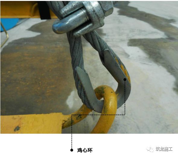
A flexible connection is set every 4.5m
.
The end is tied with the anchor ring embedded in the beam
.
4
.
In case of typhoon, the safety net should be taken back and removed
.
In order to set up the hard pick safety protection shed, we should adjust measures to local conditions, comprehensively consider the protection needs and typhoon prevention measures
.
Schematic diagram of practice of soft pick safety protective shed schematic diagram of practice of hard pick safety protective shed
.
3
.
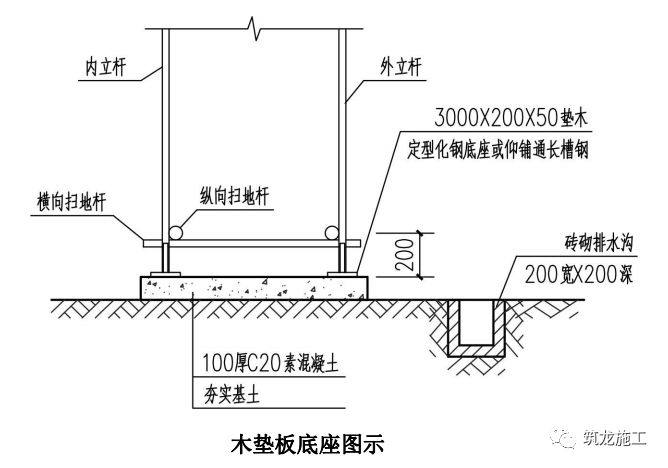
Bottom structure of floor type scaffold: 1
.
When the foundation of floor type scaffold is backfilled, two methods can be adopted: 12 channel steel base and 3000mm × 200mm × 50mm wood base
.
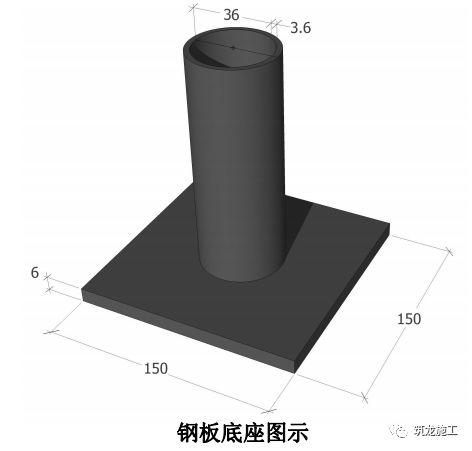
2
.
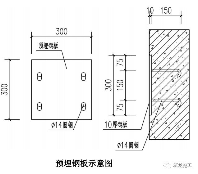
When the floor type scaffold is set on the basement roof, a 150 mm × 150 mm × 6 mm steel plate base can be used (see the diagram of steel plate base for details)
.
4
.
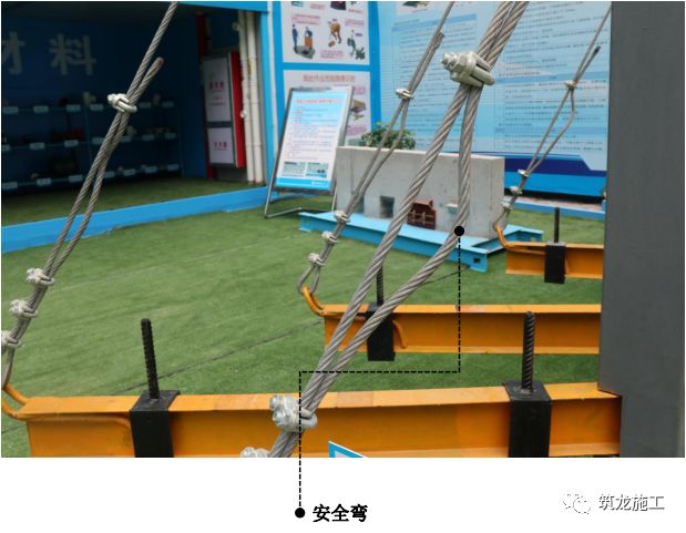
Overhanging Scaffold 1
.
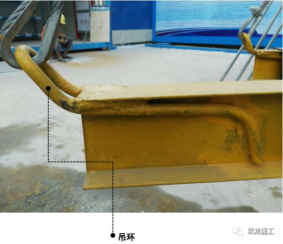
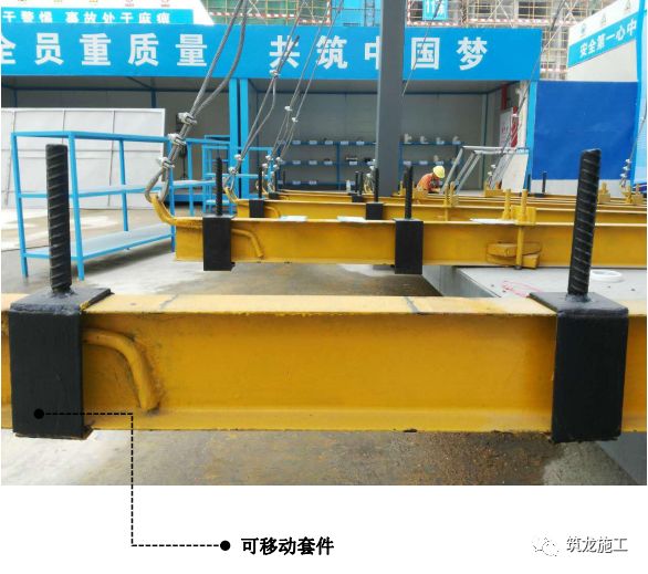
The “four new” structure of Overhanging Scaffold is convenient to check whether the steel wire rope is loose
.
When the arc of the end steel wire rope is reduced, it indicates that the steel wire rope is loose
.
It is necessary to check and tighten the buckle again
.
When the steel web is welded with the draw hook, the wire rope is directly pulled on the draw hook, and the wire rope is not easy to slide and wear when it is stressed, so as to improve the safety performance.
.