Source: if there is any infringement in Luban union of construction engineering, please contact and delete
. 
Based on the current code GB 50303-2015 “code for acceptance of construction quality of building electrical engineering”, this paper summarizes the key provisions of installation and construction of ① bridge, ② conduit, ③ cable and ④ bus, and analyzes the quality control of key processes with examples
. 
It is suggested that engineering friends exchange and study and deeply understand, so as to make us understand The electrical installation works of the project meet the specification requirements
. 
11.1.1 the connection between metal ladder, tray or slot box body shall be firm and reliable, and the connection with protective conductor shall meet the following requirements: 1
. 
When the total length of ladder, tray and slot box is not more than 30m, no less than 2 places shall be reliably connected with protective conductor; when the total length is more than 30m, a connection point shall be added every 20m ~ 30m, and the starting end and terminal end shall be reliably grounded
. 
2
. 
The two ends of the connecting plate between the non galvanized ladder, tray and trough box body shall be crossed with the protective connecting conductor, and the sectional area of the protective connecting conductor shall meet the design requirements
. 
3
. 
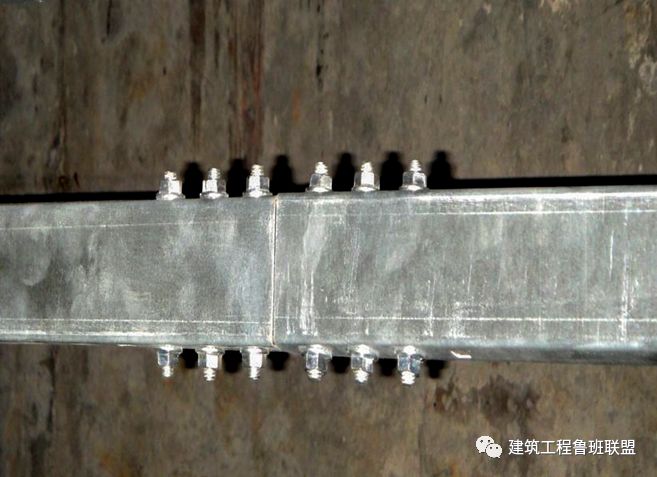
When the protective connecting conductor is not bridged between the galvanized ladder, tray and trough box body, each end of the connecting plate shall not be less than 2 connecting fixing bolts with locking nuts or locking washers
. 
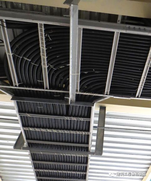
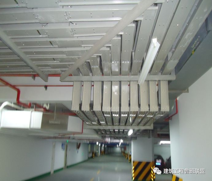
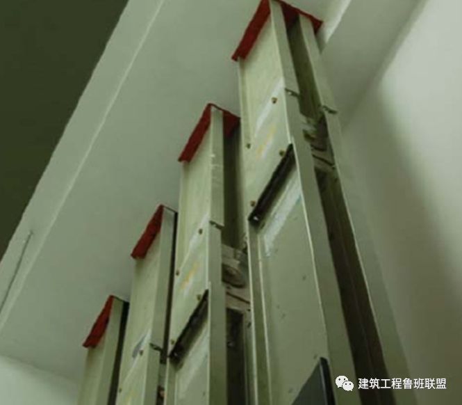
➤ installation example of galvanized ladder and trough box Z-shaped ladder transition is natural and smooth, and the support at the corner is in place
. 
The two ends of the connecting plate between the galvanized tank box body shall not be crossed with the grounding wire, but the two ends of the connecting plate shall not be less than 2 connecting fixed bolts with locking nuts or locking washers
. 
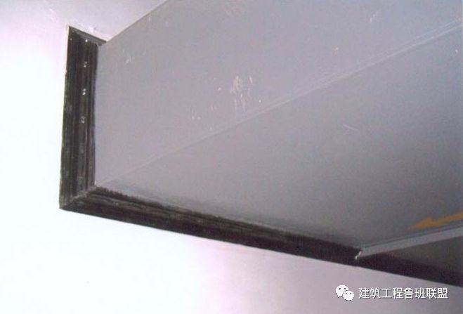
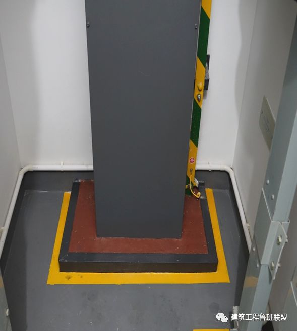
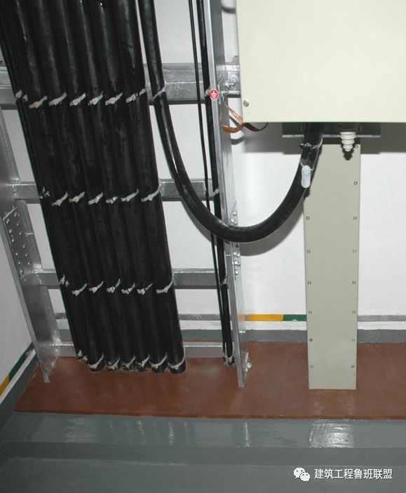
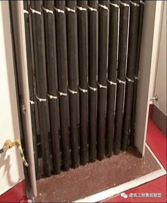
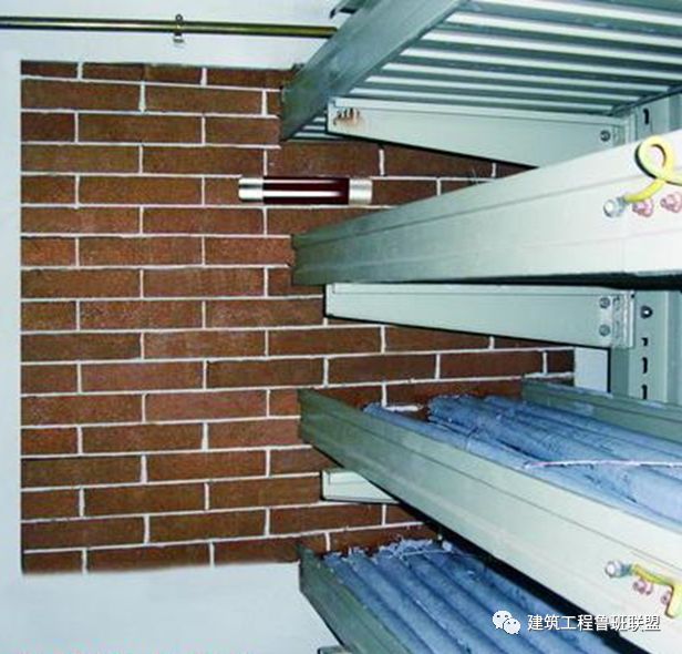
➤ electrical bridge installation example: the bridge passes through the wall and floor, and the fireproof sealing is tight
. 
The conductive part of the shell is well connected with the grounding bus
. 
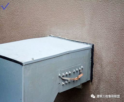
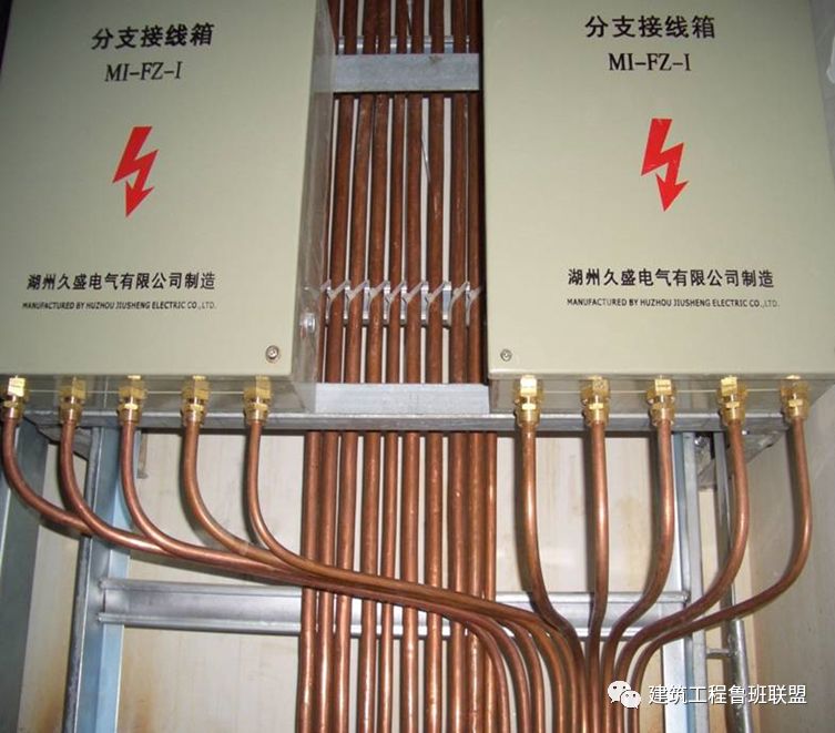
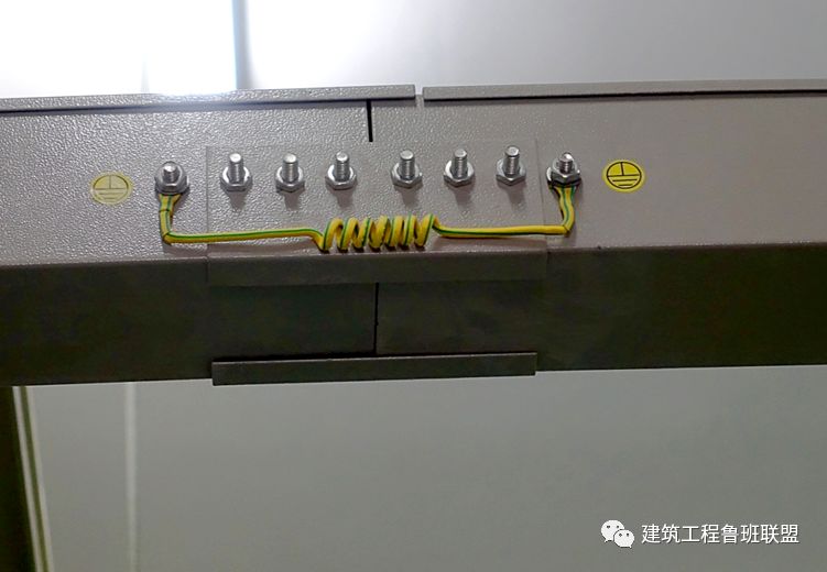
➤ installation example of grounding jumper of electrical bridge; the cross-sectional area of jumper copper wire is larger than 4mm m2, and it should be bridged at the bolt holes of special jumper at both ends of the bridge connection
. 
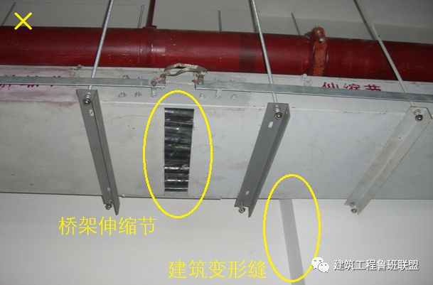
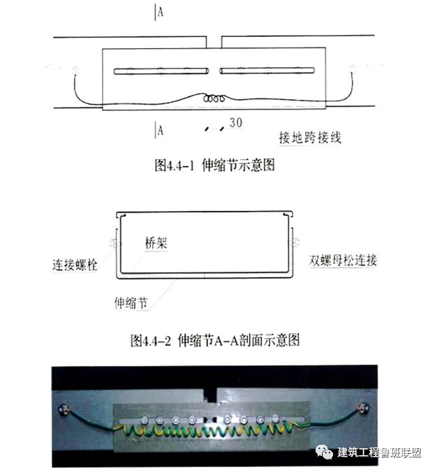
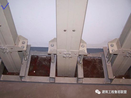
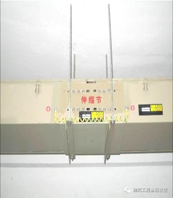
➤ installation example of expansion joint of electrical bridge through deformation joint: the expansion joint of electrical bridge is fixed firmly with connecting plate, the grounding jumper connection is perfect, and the support and hanger are installed symmetrically on both sides of the expansion joint for fixation
. 
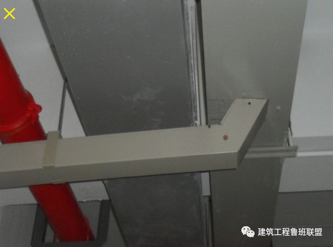
➤ installation examples of electrical bridge through deformation joint common installation problems of electrical bridge through deformation joint: ① bridge expansion joint and building deformation joint dislocation; ② electrical bridge should not be installed under the water pipe
. 
➤ electrical bridge installation error and correct comparison examples common problems: the sprinkler head is too close to the electrical bridge, water will be sprayed in the electrical bridge
. 
Correct installation: keep a safe distance between the electrical bridge and the spray head
. 
➤ analysis of installation distance between electrical bridge and sprinkler head and analysis of preventive measures: (1) there is no coordination between water and electricity disciplines of the design unit, and each of them takes care of their own, resulting in wrong positioning
. 
(2) The construction unit did not plan in advance and did not apply BIM Technology to make an overall plan for the installation
. 
(3) The professional teams of water and electricity installation are in different positions, which is caused by lack of ventilation and coordination
. 
Preventive measures: (1) carefully review the drawings before installation, and try to solve the problems during the joint review of drawings
. 
(2) Promote the application of BIM Technology, comprehensively consider the installation of various professional, overall planning, especially for some key parts, such as: machine room, basement, need BIM software to accurately locate the equipment, pipelines and components
. 
(3) Detailed disclosure to the construction team, the pipeline layout and components positioning of the three-dimensional drawings and dimensional data to the hands of the construction team
. 
(4) Supervision and inspection of construction process and re inspection after completion
. 
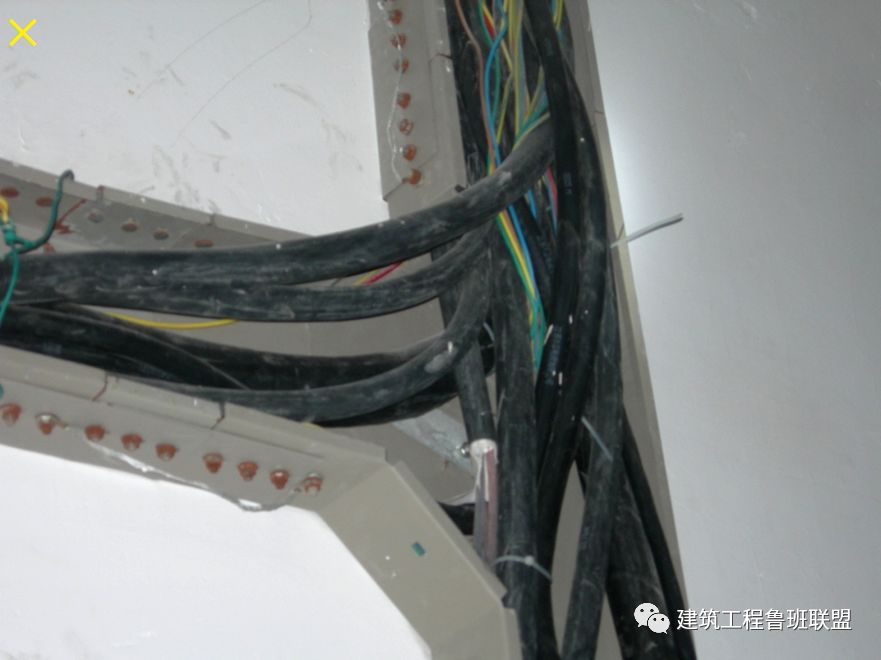
➤ the comparison between the correct and wrong installation of the electrical bridge connection part through the wall is correct: the bridge connection part should be set outside the wall for easy installation and maintenance
. 
Error: half of the connection parts are set in the wall, which is inconvenient for installation and maintenance, and the grounding jumper can not be connected
. 
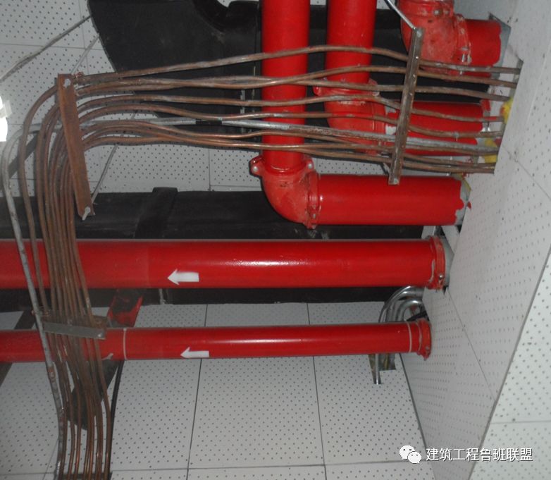
➤ the common problems of electrical bridge installation are set in the open air, the electrical bridge should have rain proof measures, and the bottom should have a drain hole
. 
12.1.1 the metal conduit shall be reliably connected with the protective conductor and shall meet the following requirements: 1
. 
Galvanized steel conduit, flexible metal conduit and metal flexible conduit shall not be welded
. 
2
. 
When the non galvanized steel conduit is connected by thread, both ends of the connection shall be welded by fusion welding to protect the connecting conductor
. 
3
. 
Both ends of the joint of galvanized steel conduit, flexible metal conduit and flexible metal conduit should be fixed with special grounding card to protect the connecting conductor
. 
4
. 
Matching parts shall be selected for mechanically connected metal conduit, pipe to pipe, pipe to box (box) connection accessories, and the connection shall meet the requirements of product technical documents
. 
When the contact resistance value of the connection meets the relevant requirements of the current national standard “conduit system for electrical installation Part 1: general requirements” GB / t20041.1, protective connecting conductor may not be set at the connection, but the conduit shall not be used A connecting conductor used as a protective conductor
. 
5
. 
When the metal conduit is connected with the metal ladder and tray, the connection end of galvanized material should be fixed with a special grounding card to protect the connecting conductor, and the connection of non galvanized material should be welded by fusion welding to protect the connecting conductor
. 
6
. 
The protective connecting conductor fixed with special grounding card shall be copper core flexible conductor with sectional area no less than 4mm2; the protective connecting conductor welded by fusion welding shall be round steel with diameter no less than 6mm, and its overlapping length shall be 6 times of the diameter of round steel
. 
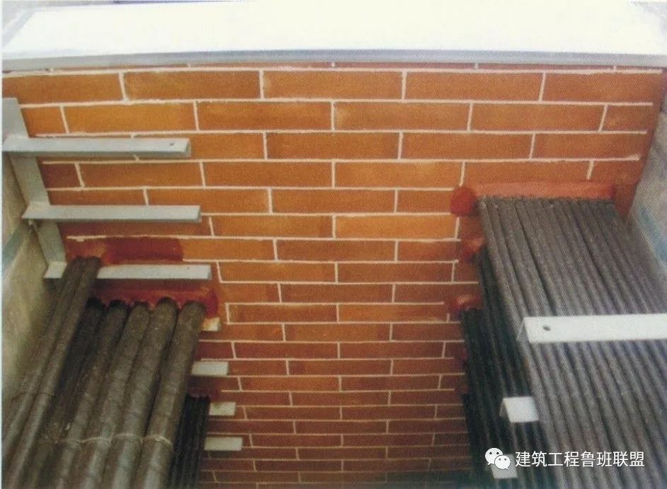
12.2.5 outdoor conduit laying shall meet the following requirements: 1
. 
For buried steel conduit, the buried depth shall meet the design requirements, and the wall thickness of steel conduit shall be greater than 2mm
. 
2
. 
The pipe orifice of the conduit shall not be open vertically upward, and the pipe orifice of the conduit shall be set in the box, box or the end of the conduit with waterproof bend
. 
3
. 
The conduit leading to the building from the box type substation or floor type distribution box, and the conduit orifice on one side of the building shall be set in the building
. 
4
. 
The pipe orifice of the conduit shall be sealed after passing through the insulated conductor and cable
.
12.2.6 the exposed electrical conduit shall meet the following requirements: 1
.
The conduit shall be arranged in order, the spacing of fixed points shall be uniform, and the installation shall be firm
.
2
.
Fixed pipe clamps shall be set in the range of 150 mm-500 mm from the middle point of terminal and elbow or the edge of cabinet, platform, box and plate
.
The maximum distance between fixed pipe clamps in the middle straight section shall meet the requirements of table 12.2.6
.
3
.
The wiring or transition box (box) used for open piping shall be open box (box)
.
12.2.8 the laying of flexible metal conduit and flexible conduit shall meet the following requirements: 1
.
When rigid conduit is connected with electrical equipment and appliances through flexible conduit, the length of flexible conduit shall not be greater than 0.8m in power engineering and 1.2m in lighting engineering
.
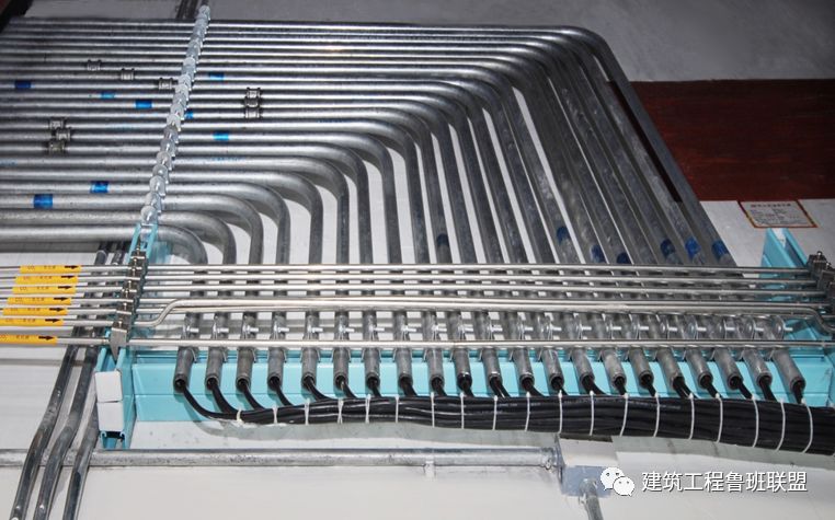
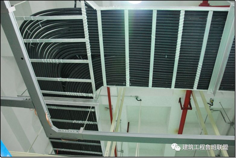
➤ the bending laying examples of electric pipes in rows are arranged in order, the pipes are parallel, the bending radius is consistent, and the arc is smooth
.
➤ example of metal hose connected to electrical facilities ➤ metal hose connected to electrical facilities with special template, safe and reliable
.
➤ pay attention to the material when using the electrical hose
.
The plastic coated metal hose shall pass the inspection of the national quality supervision and test center for fixed fire extinguishing system and refractory components according to the product requirements
.
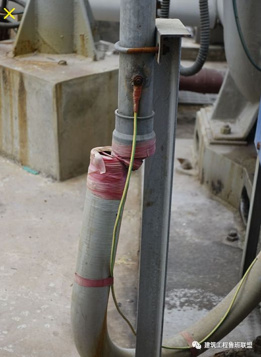
➤ common problems of electric pipe laying: the electric pipe laying is half light and half dark, and the junction with the wall body is rough
.
Special joint shall be used for conduit connection, and plastic tape shall not be used for winding, which is easy to be disconnected after aging
.
13.1.2 the cable laying shall be free from defects such as twisting, flattening of armor, fracture of sheath and severe scratch on the surface
.
13.2.2 the cable laying shall meet the following requirements: 1
.
The cable laying arrangement shall be straight and neat, and less cross
.
2
.
The minimum bending radius of the cable bend shall meet the requirements of table 11.1.2
.
3
.
Cables vertically laid in cable trench or electrical shaft or laid at an angle greater than 45 ° shall be fixed on each bracket
.
4
.
The cables laid in the ladder, tray or trough box with an inclination of more than 45 ° shall be fixed every 2m
.
For the cables laid horizontally, fixed points shall be set at both ends, both sides of the bend and every 5m ~ 10m.
.