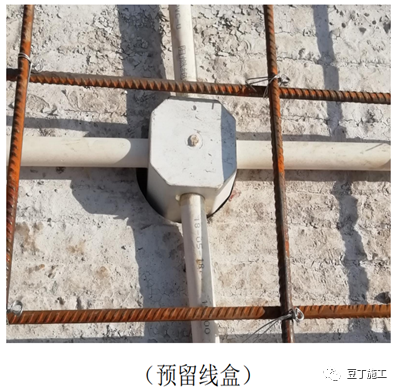
1) acceptance of prefabricated components entering the site 1) after all components enter the site, they shall be accepted one by one according to the specifications, including appearance quality, geometric dimension, embedded parts, reserved holes, etc
. 
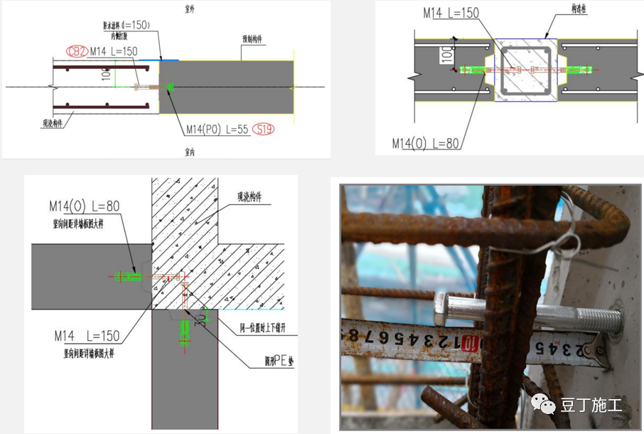
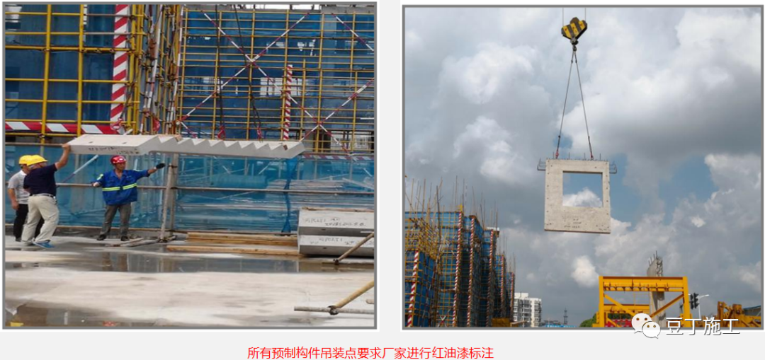
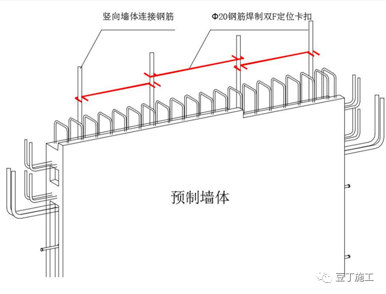
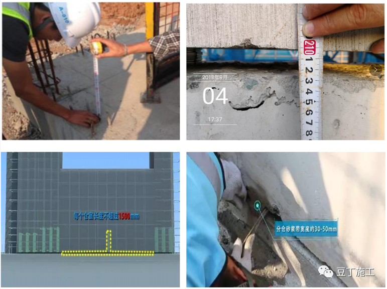
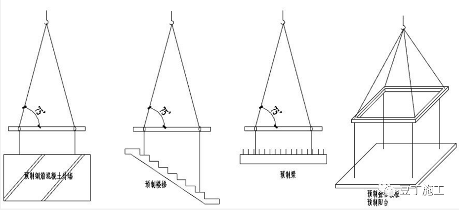
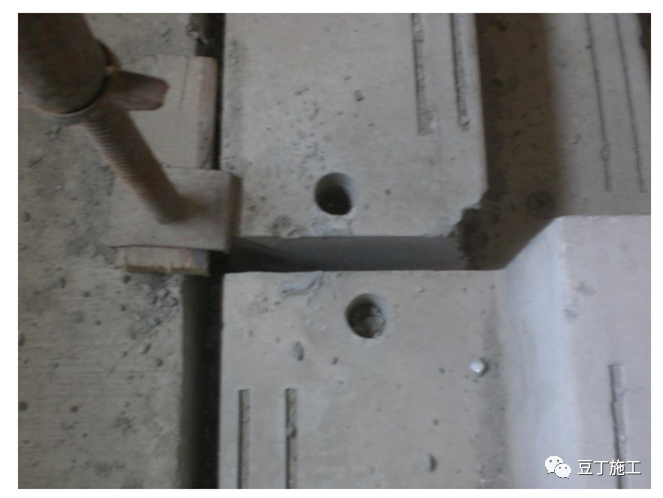
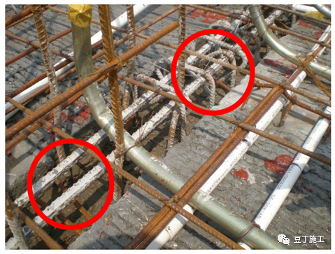
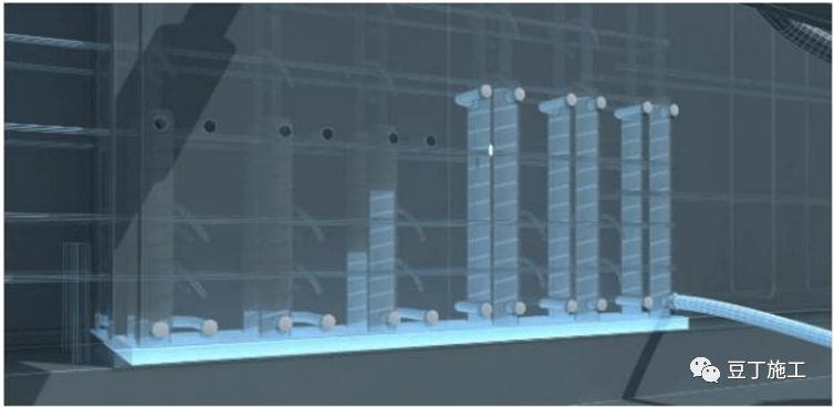
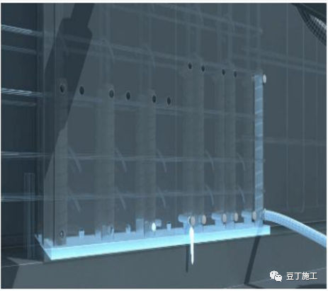
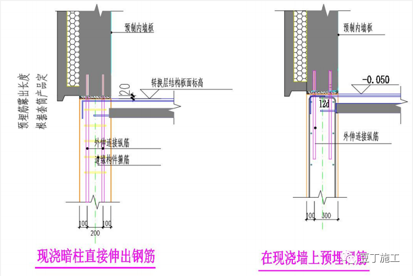
if they are found unqualified, they shall be treated; 2) all prefabricated components without lifting ring shall be required to be marked with red paint by the manufacturer for lifting points, and whether the lifting points are marked shall be checked after entering the site 2) lifting method of prefabricated components 1) design without lifting ring In case of special requirements, the PC hoisting shall be carried out with steel shoulder pole (as shown in the figure); 2) the hoisting position shall be the design hoisting point position, and the design hoisting point shall not be adjusted or hung less; 3) the positioning measures for connecting reinforcement of vertical precast wall; 1) the vertical connecting reinforcement shall be rechecked and corrected with steel welded double-F positioning buckle (as shown in the right figure), so that the precast wall and connecting reinforcement can be aligned smoothly; 2) the concrete wall can be connected with the connecting reinforcement Before the initial setting, double-F positioning buckle shall be installed to recheck the position of vertical reinforcement; 3) before the installation of vertical components, secondary recheck shall be carried out, and the deviation shall be adjusted according to the specification, and cutting of reinforcement is strictly prohibited; 4) excessive inserting of reinforcement between cast-in-place layer and assembly layer; 1) whether the diameter specification of vertical reinforcement of cast-in-place wall is consistent with that of extended connecting longitudinal reinforcement; if it is consistent, the reserved reinforcement in Figure 1 shall be used; if it is not, the reinforcement in Figure 2 shall be used (2) the location of the extended connecting longitudinal reinforcement shall be consistent with the position of the sleeve of the precast wall panel; (3) the location of the embedded reinforcement shall be accurate, and the position shall be checked according to the requirements of Article 6; (5) the vertical wall connection grouting (divided warehouse); 1) the lower four corner support pads of the precast wall panel shall be leveled, and the gasket installation shall avoid blocking the grouting hole and grouting connecting cavity; 2) the precast wall shall be hoisted in place, and the grouting shall be carried out after the adjustment When the grouting method of connecting cavity is used, each connecting grouting area (the length of the chamber) should not exceed 1500mm, and the width of the mortar Belt should be 30-50mm; 6
. 
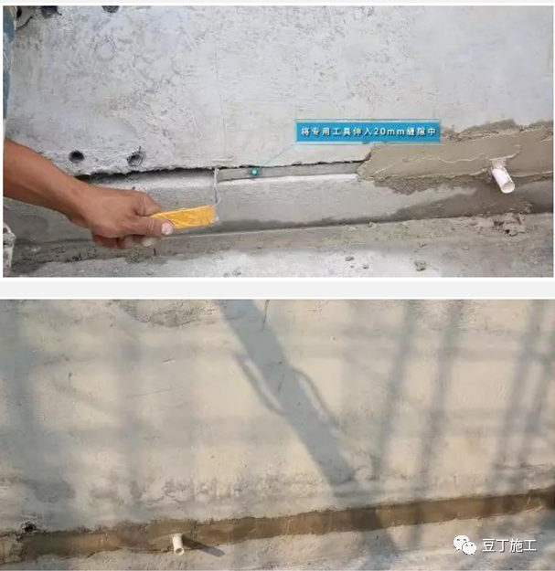
Vertical wall connection grouting (sealing) 1) special tools should be used for sealing, and 20 mm should be extended into the gap as the baffle for plastering the mortar
. 
2) After plastering the mortar, pull the baffle until it is completed; 3) the sealing quality of the mortar should meet the grouting requirements; 6) the vertical wall connection grouting (grouting) 1) the grouting process of the vertical components must be carried out by the project management personnel; 2) the grouting process should ensure the smooth grouting after the grouting hole; 3) the grouting amount should be calculated before the implementation of grouting, and the actual grouting amount must meet the requirements; 4) the grouting quality should be improved The grouting steps are as follows: 1) the grouting material mixture flows into the cavity and sleeve through the grouting hole through the conduit in the way of pressurization from the grouting cylinder; 2) when the grouting material mixture flows out from other grouting holes and slurry outlets of the component and there is no bubble, it is timely blocked with rubber plug
. 
6 vertical wall connection grouting (leakage treatment) 1) leakage treatment during grouting: stop grouting and deal with the leakage part
. 
In case of serious slurry leakage, it is necessary to lift the prefabricated wallboard to seal the warehouse again; 2) slurry leakage treatment after grouting: secondary grouting shall be carried out, and the pressure of secondary grouting shall be slightly lower than that of grouting, and the slurry outlet near the leakage part shall be opened during grouting
. 
The grouting hole nearest to the leakage part is selected for grouting, and the grouting shall be blocked after the slurry flows out without bubbles, and the grouting shall be carried out in sequence; 6
. 
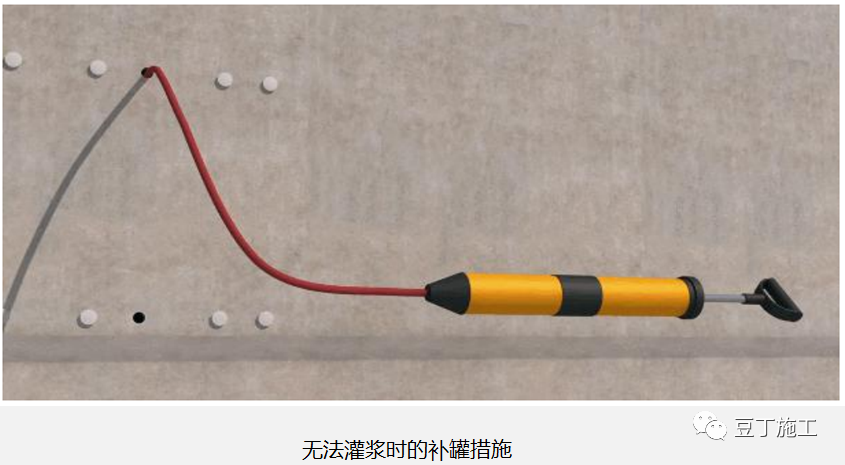
Vertical wall connection grouting (no grouting treatment) 1
. 
When the grouting material is mixed with water, the grouting shall be made up in the grouting hole within 30 minutes; 2) when the grouting material can no longer flow, the grouting can be made up from the grouting hole, and the grouting shall be made from the grouting hole by manual equipment combined with thin pipe
. 
7
. 
Connecting bolts between precast wall and cast-in-place wall 1) the tightening torque of connecting bolts between precast wall and cast-in-place wall shall meet the requirements of jgj107-2016; 2) the exposed marks of bolts at each node shall be specified according to the design requirements for the convenience of inspection
. 
8
. 
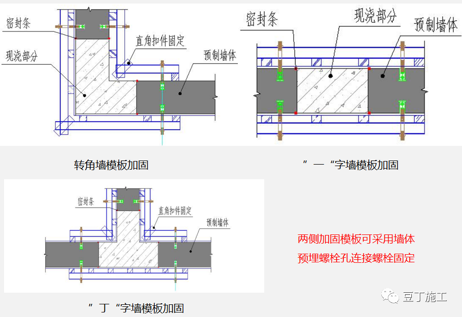
Formwork method at the intersection of precast wall: 1) through wall bolt holes for formwork reinforcement shall be reserved for precast wall; 2) the number and spacing of through wall bolt holes for formwork reinforcement shall meet the requirements of cast-in-place wall formwork reinforcement; 3) sealing strips shall be pasted on the edge of precast wall to prevent slurry leakage
. 
9
. 
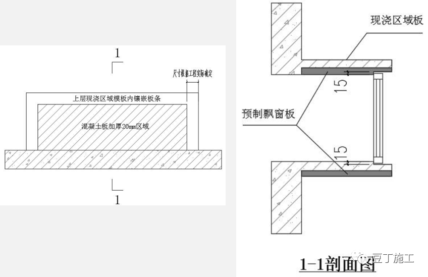
Practice of water stop tongue and groove for precast exterior wall panel: 1) tongue and groove shall be set outside the precast exterior wall panel to reduce rainwater seeping into the room along the joints; 2) the tongue and groove pattern shown in the figure is only an example, not the only one, and the tongue and groove pattern can be set for each project according to the actual situation of the project; 3) tongue and groove practice is proposed in the deepening design
. 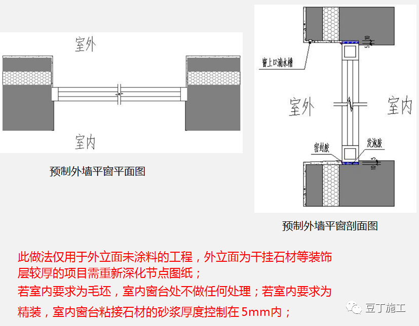
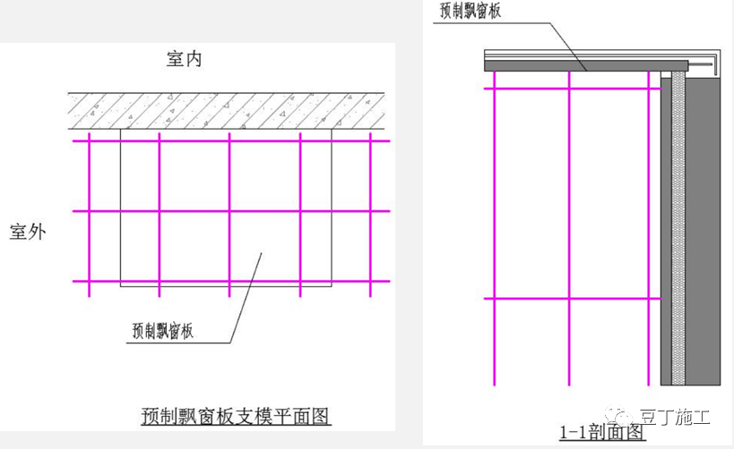
1) when the drawing of precast exterior wall is deepened, tongue and groove shall be added around the window opening to prevent rainwater from seeping into the room; 2) the horizontal position of external window installation shall be determined according to the actual project, and the section in the drawing is a schematic; 11) tongue and groove shall be set for precast bay window plate; 1) when the drawing of precast bay window plate is deepened, tongue and groove shall be added to the upper and lower Bay plate to prevent rainwater from seeping into the room; 2) installation of external window The horizontal position is determined according to the actual project, and the section in the figure is a sketch
. 
12
. 
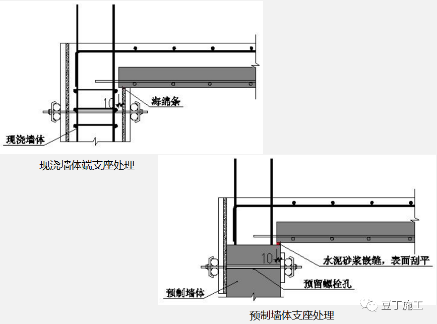
Anti leakage measures for end support of laminated plate: 1) cast in situ shear wall: paste full-length sponge strip on the top of wall formwork to prevent mortar leakage at the connection part; 2) prefabrication of shear wall: bolt holes through the wall are reserved at the top of the wall, and the external formwork is fixed by the through wall holes
. 
The joint between the wall and the laminated board is caulked with cement mortar, and the surface is scraped flat
. 
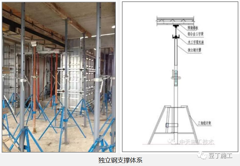
13 laminated plate support system (independent support) 1) the top of independent steel support is set with beam (10 * 10 wood or metal beam); 2) the beam spacing is not more than 1.8m
. 
The distance between the crossbeam and the wall is not more than 0.5m; 3) the distance between the independent support along the crossbeam direction is not more than 2.0m, and the distance from the wall is not more than 0.5m; 4) the direction of the support crossbeam: it is perpendicular to the long side of the composite slab, and the two-way slab is perpendicular to the cast-in-place slab; 5) the formwork support of the cast-in-place floor is considered separately
. 
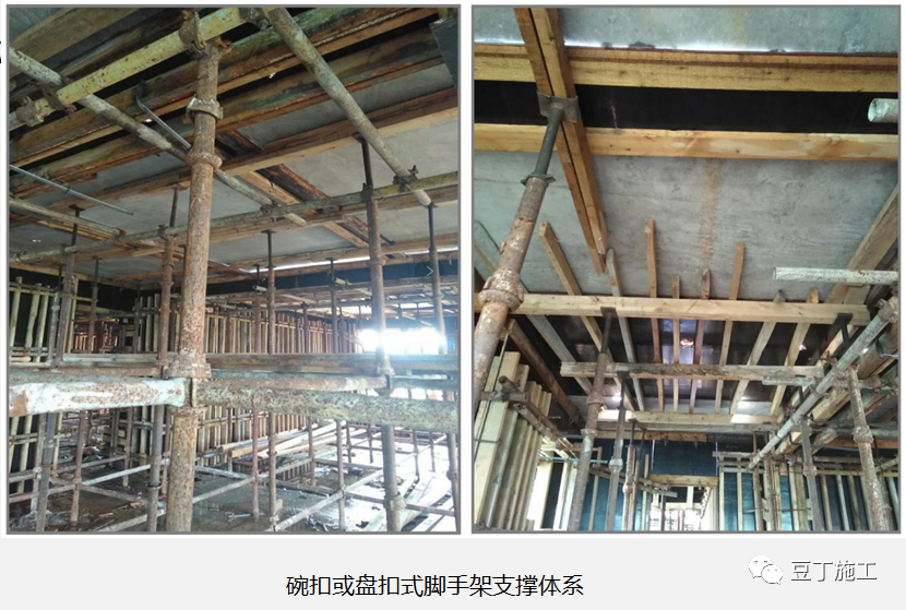
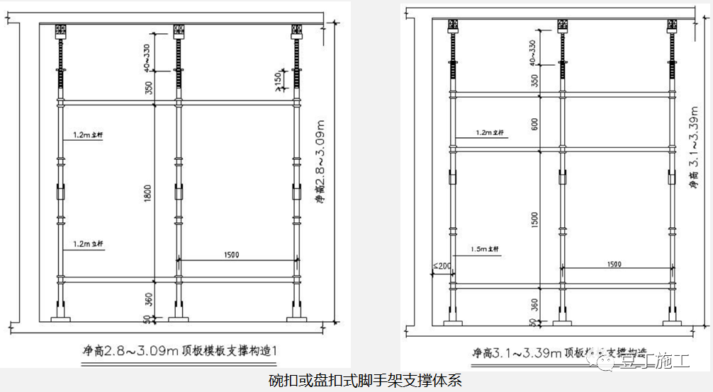
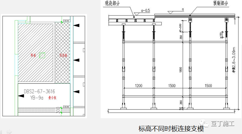
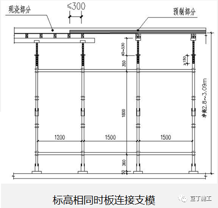
13 laminated plate support system (non independent support) 1) adopt bowl buckle or wheel buckle and other forms of support, and the middle is connected by cross bar, which is not more than 0.5m away from the wall; 2) the vertical and horizontal spacing of vertical bar is not more than 1.5m, and the height of support free end is not more than 650mm; when the floor height is not more than 3.1m, two horizontal bars can be set; 3) the main keel is made of square steel pipe or 100 * 100 square wood; 4) when the keel is laid, it is combined with cast-in-place floor formwork Worry
. 
1) when the elevation of the composite plate and the cast-in-place plate is the same, the formwork supporting system shown in Fig
. 
1 shall be adopted; 2) when the elevation of the cast-in-place plate is inconsistent, the supporting method shown in Fig
. 
2 shall be adopted
. 
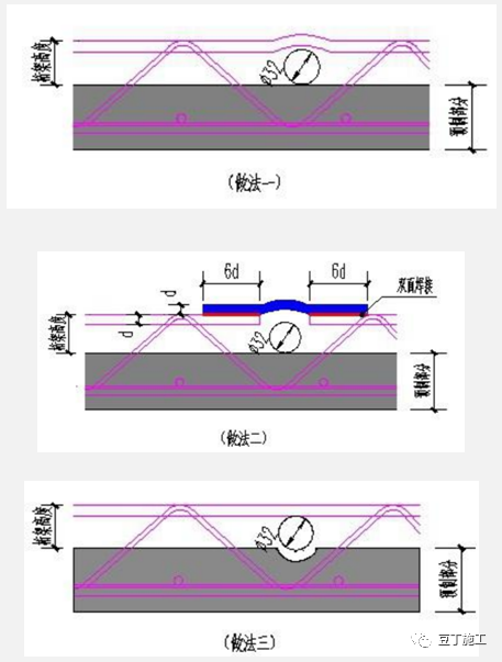
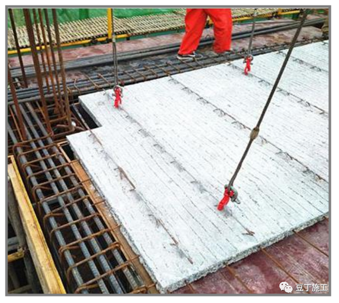
14 steel bar binding on the upper part of the composite slab 1) when deepening the design of the cast-in-place thickness, it must be considered whether the total thickness of the surface layer steel bar after binding still meets the requirements of the thickness of the steel bar protective layer; 2) the reinforcement of the upper layer cast-in-place slab of the composite slab is tightly bound with the truss reinforcement (especially the root of the shear wall), so as to prevent the steel bar from warping and exposing; 3) the steel bar on the surface layer of the slab should be designed and bound on the truss, and should not be worn The truss is bound below (the construction is too difficult)
. 
15, the installation of overlapped plates and the intersection of main beams of the girder should be treated at the intersection of the main reinforcement and the main reinforcement at the ends of the joint
. 
The main reinforcement should be tied up before construction, the main reinforcement should be adjusted before installation of the composite board, and the main reinforcement should be tied up after the installation of the composite board
. 
16
. 
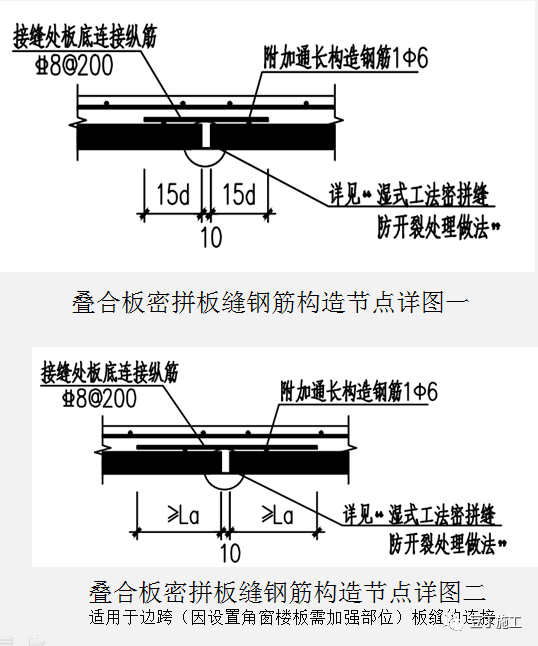
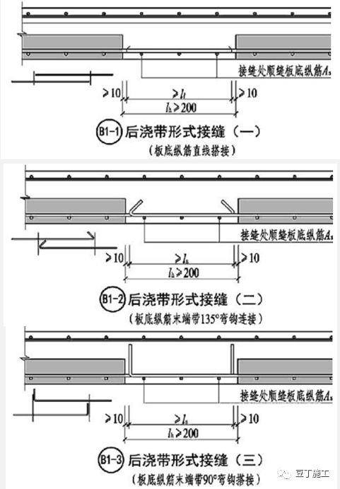
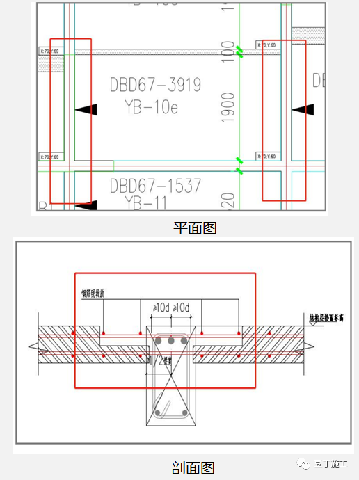
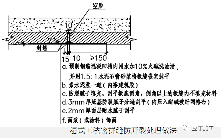
Joint structure of post cast strip form of composite slab 1) joint of post cast strip form of two-way slab, the specific reinforcement connection mode can adopt the three kinds shown in the right figure, and the specific method is determined according to the design; 2) when the joint of one-way slab is designed as post cast strip form, additional reinforcement of slab joint shall be added at the joint position; 3) when pouring the post cast strip of composite slab, it must be vibrated in place to ensure the connection quality
. 
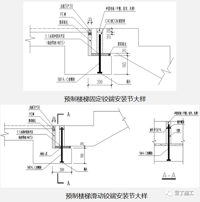
17 connection method of precast stair 1) the elevation of precast stair slab shall be carefully verified before installation; 2) the connection mode of precast stair slab is fixed hinge support at the upper part and sliding hinge support at the bottom; (selected from 15g367-1) 3) the grouting hole of fixed hinge support shall be protected when not grouting to prevent impurities from entering the duct, and the density of grouting material shall be strictly controlled during grouting; 18) the elevation control of precast stair 1) The elevation of precast stair platform shall be consistent with that of cast-in-place ladder beam structure
. 
2) 30mm plastering or tiling shall be reserved for surface course.
.