Source: the copyright of CCCC belongs to the original author
. 
The first part is site layout
. 
The construction site mainly includes three parts: diaphragm wall forming area; slurry system area; reinforcement cage processing area
. 
The three areas are connected by access road, and the mud system pipeline shall be arranged to the wall forming area of diaphragm wall
. 
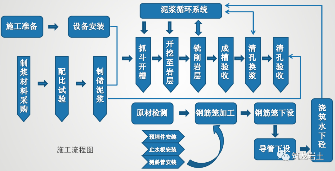
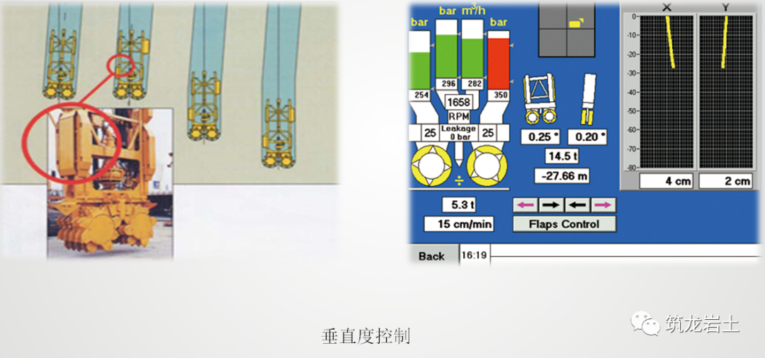
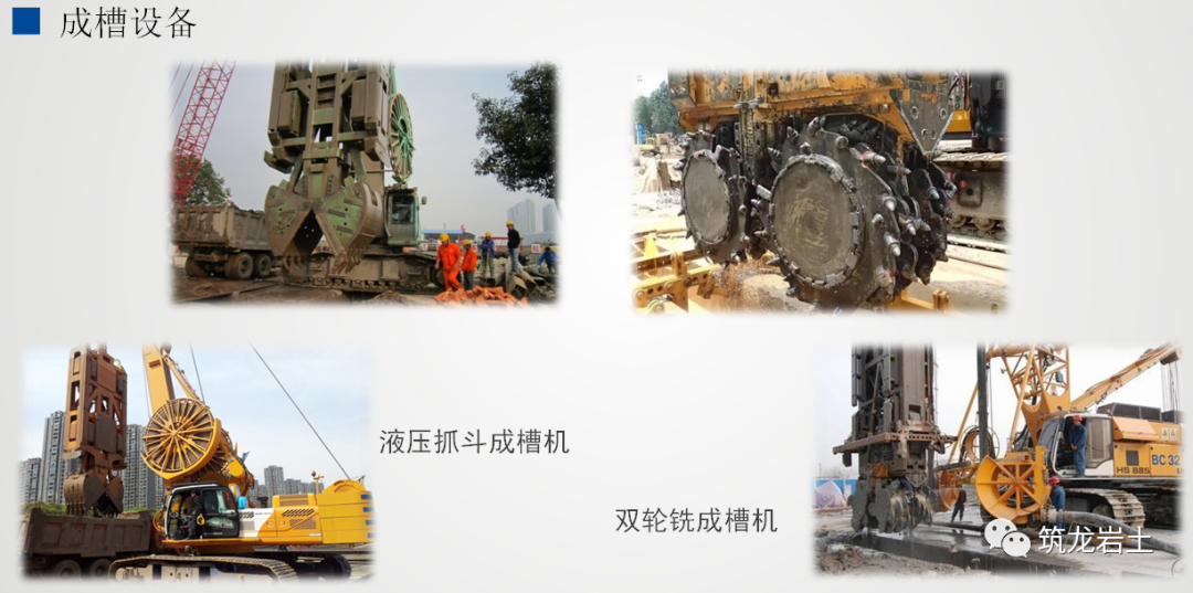
According to the geological and structural characteristics, the diaphragm wall construction of the project adopts the “combination of grab and milling” trenching technology, that is, the shallow silt and clay composite stratum adopts the hydraulic grab trenching, and after entering the rock stratum, the trenching machine is used for trenching construction
. 
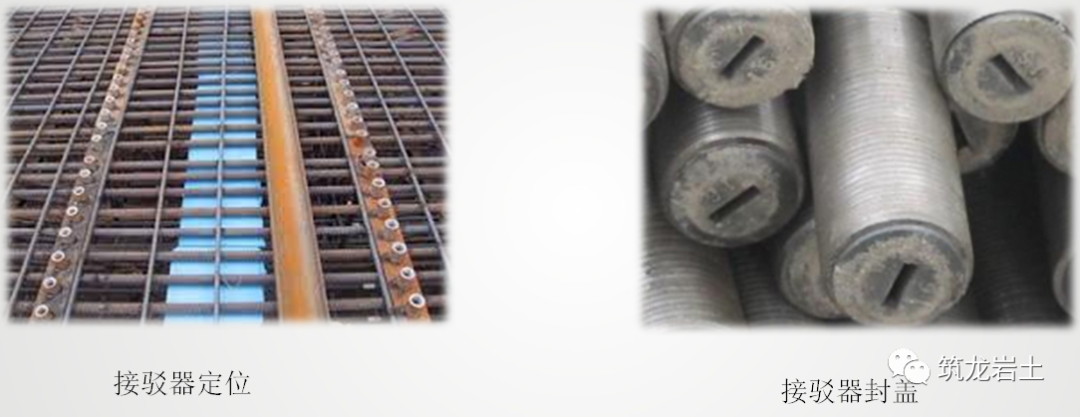
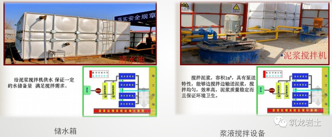
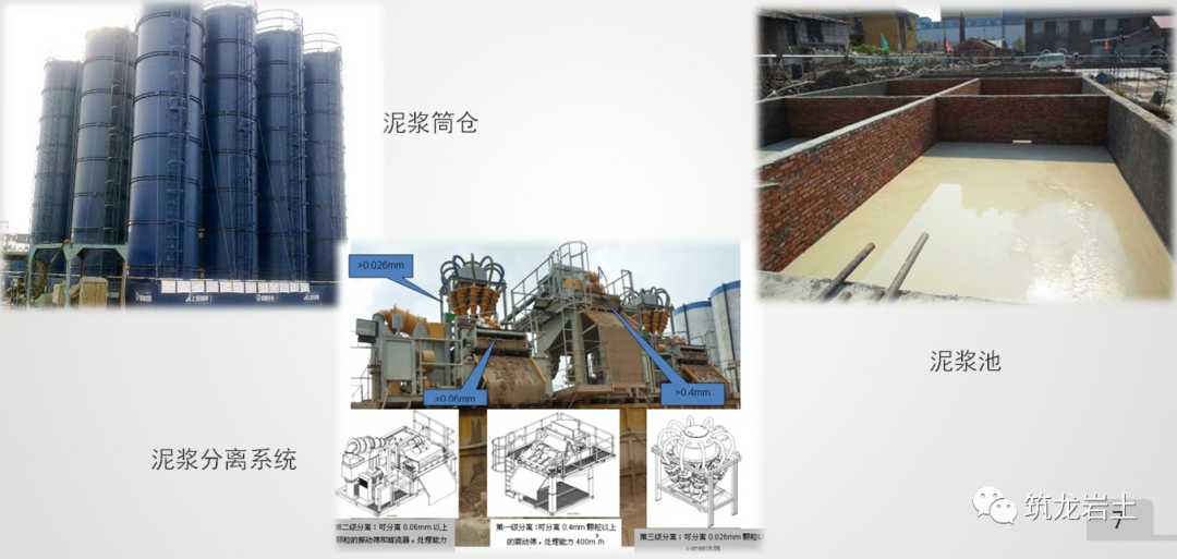
In order to minimize the floor area of the mud system, the mud system combining the mud silo with the in-situ mud pit is adopted
. 
The mixing, screening and circulation of mud are mainly completed in the mud pit, and the storage mainly depends on the mud silo
. 
The mud silo is divided into two systems which are not connected with each other
. 
Silo group A stores the grooved mud, while the mud stored in silo group B is specially used for bottom cleaning and slurry exchange
. 
In principle, the reinforcement cage processing area of diaphragm wall is set near the grooving area of diaphragm wall to facilitate the transportation and installation of reinforcement cage
. 
On the basis of compacting the original ground, gravel is laid and concrete surface is poured
. 
The size of the processing site is set according to the size of the longest segment of the reinforcement cage
. 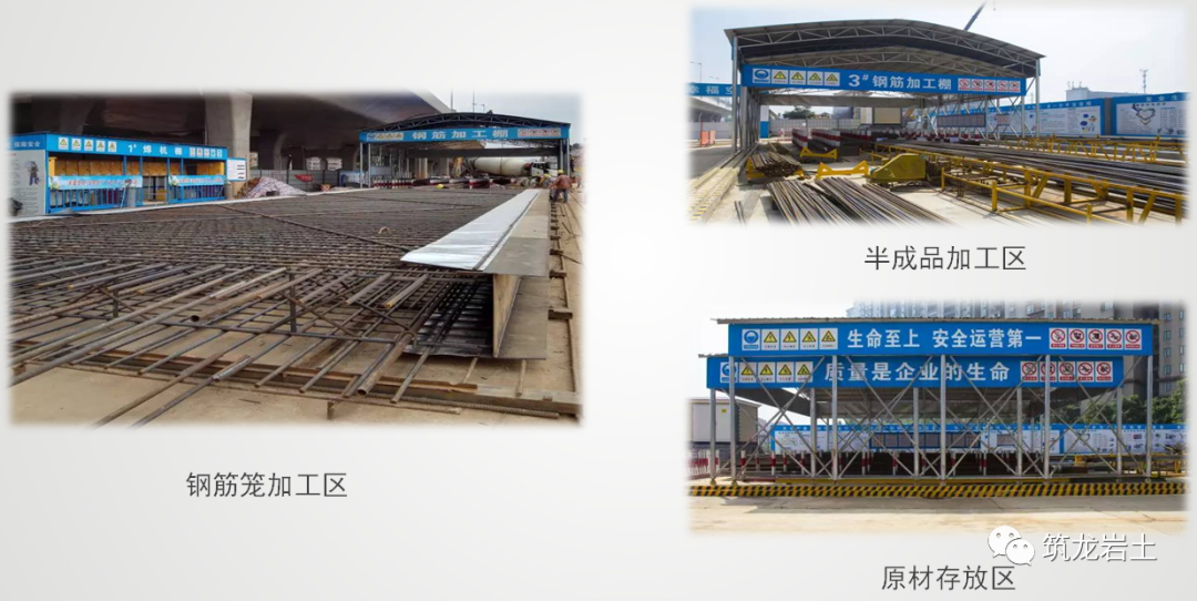
The reinforcement cage is processed as a whole by the unit slot section
. 
The site can process the reinforcement cage of two slot sections at the same time
. 
Raw material storage area, semi-finished product processing area and reinforcement cage stacking area shall be set near the reinforcement processing site
. 
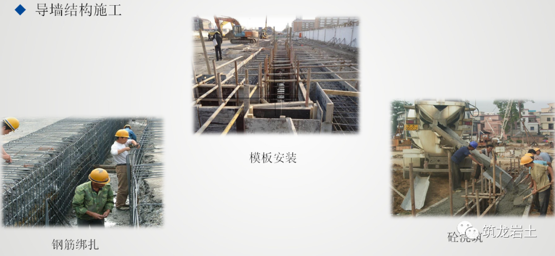
The second part is the construction technology
. 
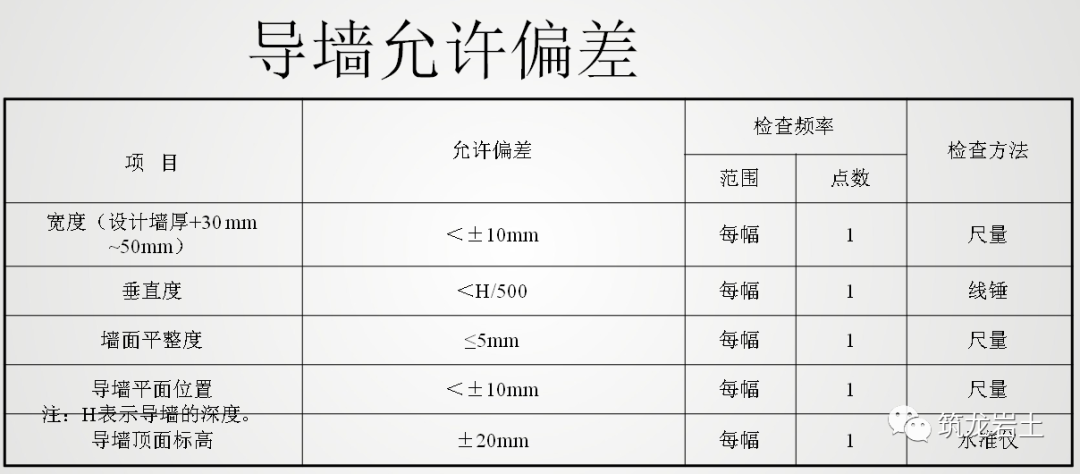
The manufacture of guide wall is the key to ensure the accurate position and grooving quality of diaphragm wall
. 
During the construction period, the guide wall often bears the static and dynamic loads such as reinforcement cage, conduit for pouring concrete and mechanical equipment
. 
Therefore, it must be carefully designed and constructed before the formal construction of diaphragm wall can be carried out
. 
Function: to guide the grooving machine to form the groove; to store the slurry and prevent the collapse of the groove; to serve as the benchmark for horizontal and vertical measurement during construction; the guide wall generally adopts the cast-in-place reinforced concrete structure, and also has the fabricated structure of steel or precast reinforced concrete
. 
According to the characteristics of different soil design and construction
. 
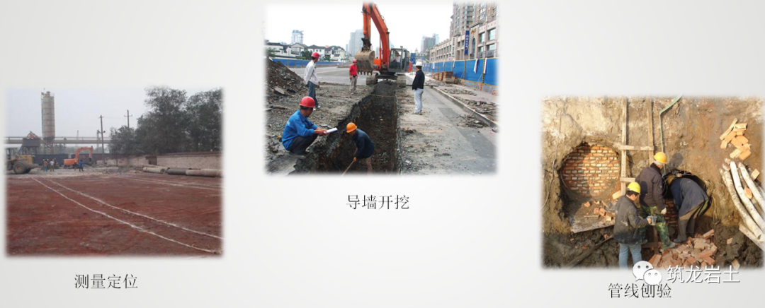
The outer boundary of the main structure shall be measured and lofted according to the coordinates of the drawing
. 
The center line and side line of the guide wall shall be reflected through the outer boundary
. 
The center line of the guide wall shall coincide with the center line of the diaphragm wall
. 
Measure the ground elevation and the depth according to the drawing requirements, so as to carry out the excavation of the guide wall
. 
Due to the internal displacement and deformation of diaphragm wall under the action of external earth pressure during foundation pit excavation, in order to ensure that the clearance of foundation pit structure meets the requirements in the later stage, the center line of guide wall is generally set out, and the discharge amount is determined according to the design requirements and the structure depth
. 
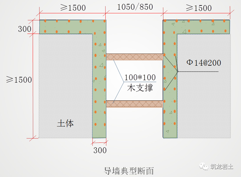
The guide wall is 1.5m higher than the underground water level, the toe of the wall is more than 300 mm into the undisturbed soil layer, and the bottom elevation of the guide wall is more than 20 cm lower than the top elevation of the diaphragm wall
. 
If the undisturbed soil in the construction area of the guide wall is damaged, the soil is loose, and the toe of the wall cannot enter the solid undisturbed soil layer, the soil shall be reinforced before the construction of the guide wall
. 
According to the pipeline position on the pipeline map, the pavement above the area where the pipeline needs to be cut and modified shall be broken
. 
The specific location of the pipeline is detected
. 
After the pipeline is broken, the cross section of waste gas pipeline is blocked, and the area is backfilled with cement soil
. 
The formwork shall be removed after the concrete strength reaches 5MPa
. 
After the removal of the formwork, the central axis and clearance size of the guide wall and the pouring quality of the side wall concrete shall be checked again immediately
. 
If the side wall concrete intrudes into the clearance or there is a hole in the wall, it shall be repaired or sealed in time
. 
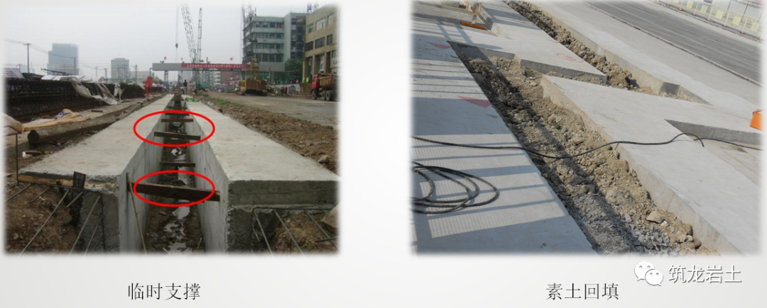
After the formwork is removed, wooden supports shall be erected immediately, one above and one below, arranged in quincunx shape, with a spacing of 1.0 ~ 1.5m
. 
After passing the inspection, the earthwork shall be backfilled immediately to prevent the displacement of the guide wall
. 
Before the concrete of the guide wall reaches the design strength, it is forbidden for any heavy machinery and transportation equipment to pass by it
. 
At the same time, the top wing surface of the guide wall shall be marked with a framing line with red paint, and the construction joints of the guide wall and the underground wall shall be staggered
. 
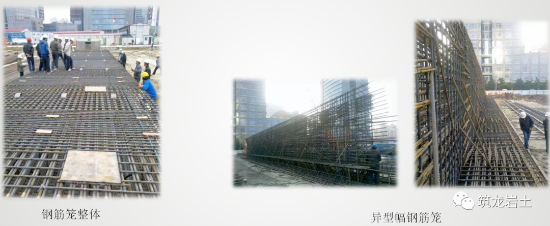
Manufacturing of reinforcement cage according to the design drawing of reinforcement cage, draw the processing drawing of reinforcement cage before manufacturing
. 
According to the layout requirements of the pipe, the position of the pouring pipe shall be reserved in advance
. 
Two grouting pipes are welded on the proper position of the reinforcement cage according to the design
. 
The reinforcement connector is set on the reinforcement cage according to the layout of the main structure
. 
The monitoring components of foundation pit are embedded in the reinforcement cage according to the design requirements
. 
All embedded parts shall be installed accurately
.
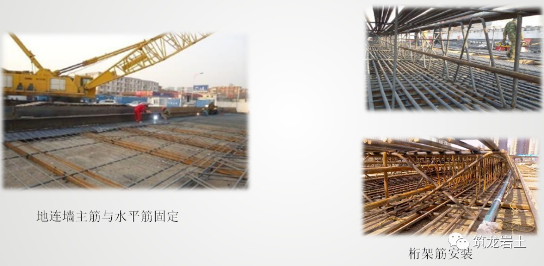
At present, the commonly used process of flexible joint diaphragm wall reinforcement cage is as follows: steel processing platform erection – bottom horizontal reinforcement and joint fixation – bottom main reinforcement and horizontal reinforcement fixation – longitudinal truss – transverse Truss – top main reinforcement – top distribution reinforcement – lifting point reinforcement and joint reinforcement
.
The steel cage processing platform should have strong rigidity and stability to prevent the deformation of the steel cage due to its own weight
.
In practical operation, channel steel, I-steel and other profiles can be used to weld with reinforcement to form a platform, and the length of the platform is determined according to the length of the reinforcement cage
.
In order to prevent irrecoverable deformation of reinforcement cage during lifting, longitudinal and transverse truss bars are set for reinforcement cages of various shapes
.
During construction, truss bars are welded in strict accordance with design and specification requirements to ensure the rigidity of reinforcement cage
.
The equipment needed for monitoring, such as inclinometer, acoustic pipe, earth pressure gauge, etc., shall be reasonably arranged during the fabrication of diaphragm wall reinforcement cage to avoid conflict with subsequent concrete conduit
.
All exposed cables must be fixed and tightly wrapped through casings to prevent displacement in the process of reinforcement cage hoisting and concrete pouring, and the monitoring work cannot be carried out due to grouting in the pipe
.
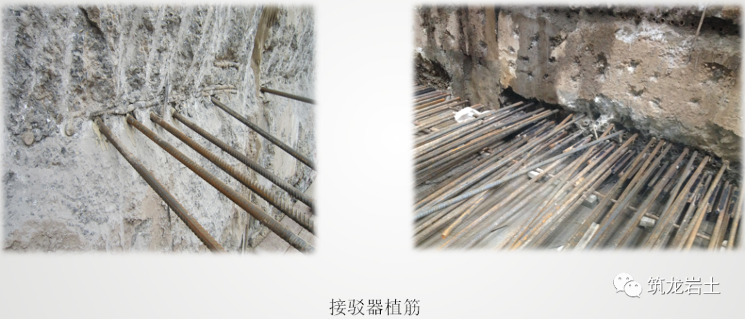
The reinforcement connector of the diaphragm wall is the connector embedded on the reinforcement cage of the diaphragm wall for the integral connection of the diaphragm wall and the floor according to the elevation requirements of the future underground structure floor during the reinforcement construction of the diaphragm wall, There are many problems in embedded connectors, such as connector corrosion, wire tooth damage, large azimuth deviation, which cause the connector and the main reinforcement of the structure can not be connected, screwed in place, difficult to connect and so on
.
As a result, some connectors can not be connected with the reinforcement of the main structure, which affects the integrity of the structural wallboard, so it is often necessary to plant additional reinforcement to connect
.
Cause analysis: ① the flatness of the reinforcement cage itself is not enough, the connector and the distribution bar are in point contact, the positioning is difficult to control, and the welding place is easy to produce deformation
.
② After the excavation of the foundation pit, the thread teeth of the connector are damaged when the diaphragm wall is roughened
.
③ During the lifting process, the guide cage cover collided with the wall slot
.
④ The settlement of reinforcement cage is not considered in the connector reservation
.
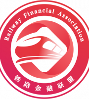
Through the quality problems of the connector construction, the improvement of the construction quality of the two-point connector is considered to overcome the disadvantages of the positioning deviation of the connector, the damage and corrosion of the thread
.
To ensure the accurate positioning of the connector and meet the construction requirements, the connector must be positioned and controlled before welding and fixing on the reinforcement cage
.
Therefore, the solution is to increase the connector “positioning card” device
.
Angle steel can be used
.
The angle steel is horizontally spot welded at the elevation of the cage connector to replace the traditional method of pulling wire
.
The height control of the connector is based on the side line of the angle steel
.
The connector is built on a plane of the angle steel and fixed by welding after positioning
.
The strip-shaped cover plate is designed to look like an “L” shape
.
After the separate cover of the connector is screwed to the position, the strip cover plate is inserted along the connection direction of the connector
.
Generally, aluminum color steel plate is used to make strip replacement, and the cover is sealed along the connecting direction of the connector, and the fine iron wire is tightened
.
When the protective layer of diaphragm wall is chiseled, theoretically, the protective layer of connector section will also fall in strips
.
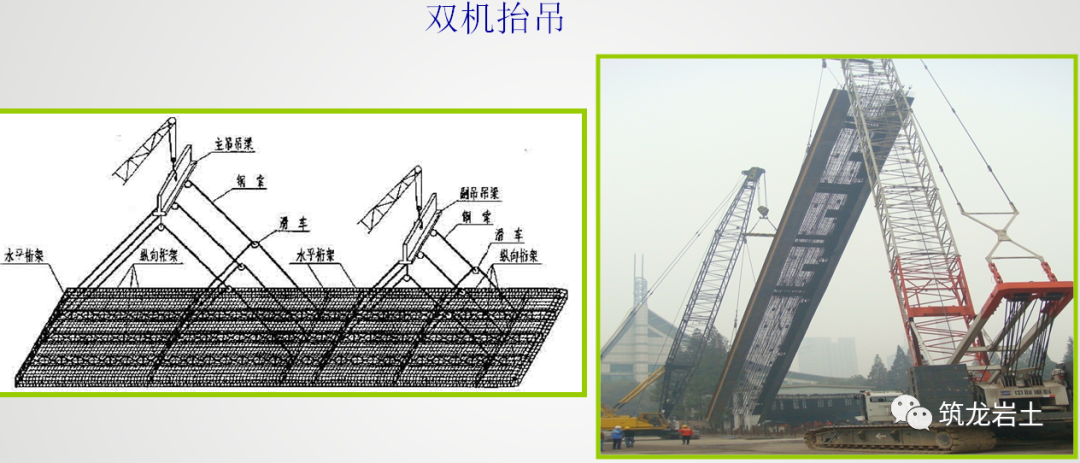
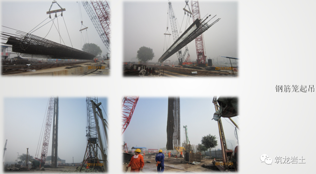
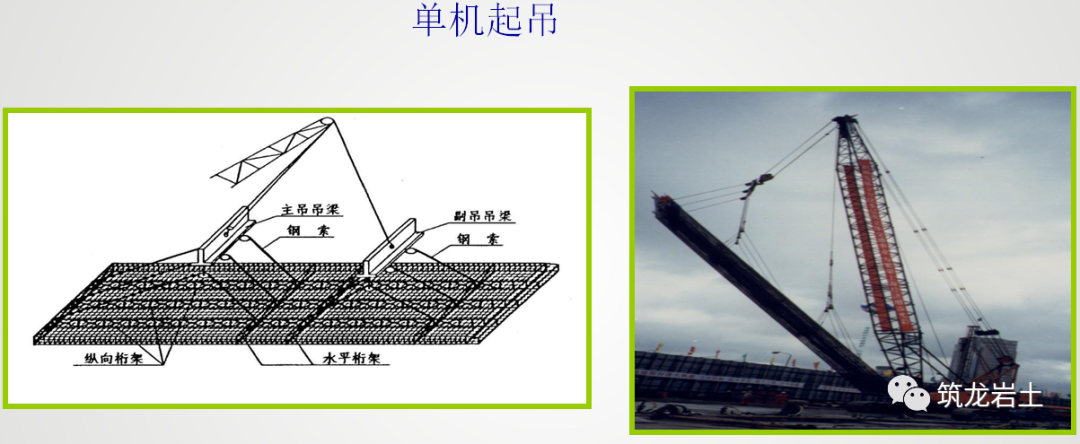
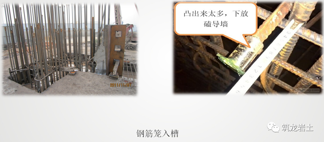
The lifting of steel cage is usually carried out by crawler crane, because after the steel cage is lifted, the crane needs to transport the vertically lifted steel cage to the orifice for lowering
.
According to the weight and length of the reinforcement cage, the matching crane shall be selected for lifting and placing
.
Generally, the single machine lifting and double machine lifting methods shall be adopted, and the special person shall be responsible for the unified command.
.