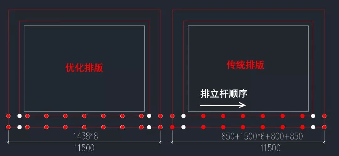
Let’s compare the traditional typesetting method and the optimized typesetting (i.e
. 
the method mentioned in this paper) with the two drawings first
. 
The effect of setting up (the white spot in the figure is the increase of vertical pole in the well shaped frame, mainly observing the different typesetting at the corners of the outer frame): ① the cross bracing is straight and crossed on the vertical pole; ② the cross bracing is not straight and straight, and then the vertical pole is not crossed
. 
Step 1: after getting the construction drawings, determine the main layout In order to determine the distance between the inner vertical pole and the main structure of the scaffold, the traditional wood formwork is generally used, and the distance between the inner vertical pole and the main structure is about 350mm
. 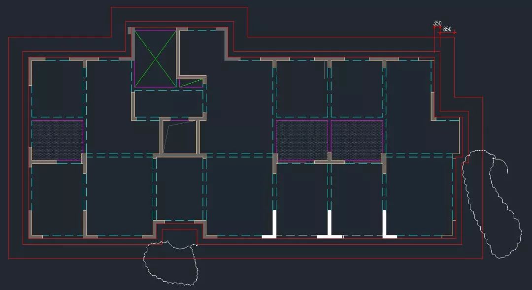
Use CAD drawing, use multiple line segments (Shortcut PL), draw closed line along the building exterior wall sideline (air conditioning board does not need to consider, directly through, the red line in the drawing is the closed line frame)
. 
The second step is to offset the closed wire frame outward by 350mm (the distance is the distance between the inner vertical pole and the main structure)
. 
Then offset the offset wire frame outward again by one frame width (the table in jgj130-2011 shows that the frame width is 1050 ~ 1300mm, most of which are 850mm in actual construction, which is explained here according to 850)
. 
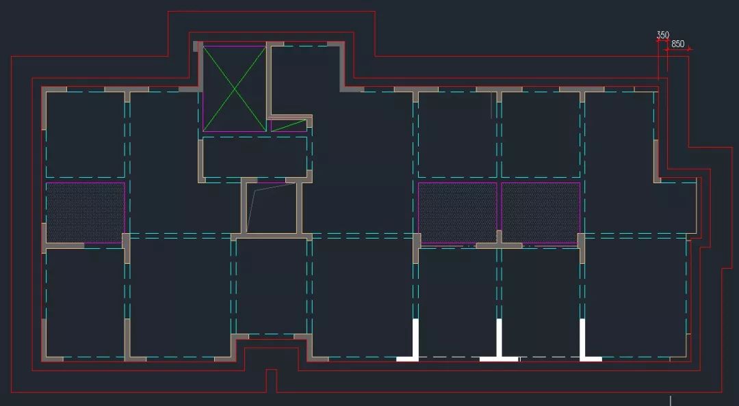
The third step is to connect the internal and external vertical poles of the scaffold
. 
If there is a relatively small staggering part, you can pull it through directly
. 
Otherwise, the scaffold will have too many corners, which will be more difficult to set up More trouble
. 
Compare the picture above with the picture below (the cloud coil is directly connected)
. 
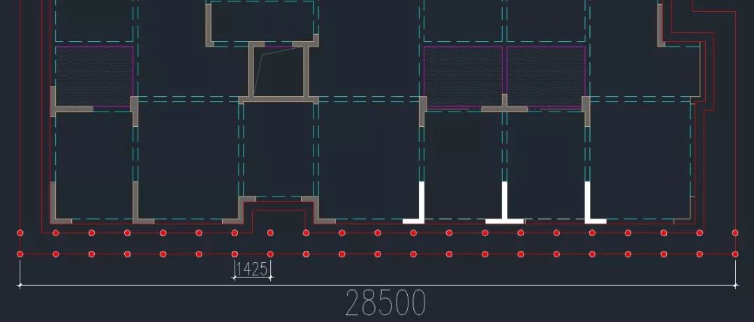
The fourth step, in order to facilitate the arrangement of the outer frame cross bracing, if there is no special case, it is uniformly stipulated that the cross bracing spans 5 vertical poles, that is, 4 longitudinal distances
. 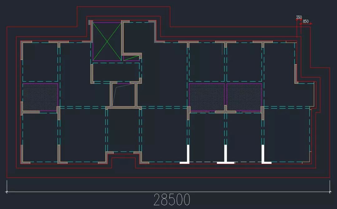
Use CAD measuring tools to measure the length of an elevation of the scaffold (the side line of the scaffold external vertical pole)
. 
As shown in the figure, the measured length is 28500
. 
The fourth and most important step is here
. 
Don’t blink
. 
In our general practice, the longitudinal distance of scaffold is 1500mm
.
Divide this data by 1500, and the number will be even
.
The specific calculation is as follows: 28500 ➗ 1500=19。 It is just divided into 19 longitudinal distances
.
According to our principle of even number span, it is arranged according to even number nearby, that is, it is calculated according to 18 longitudinal distances, or 20 longitudinal distances
.
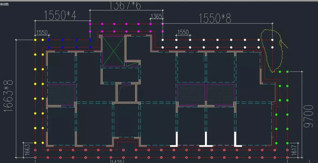
Here, it is calculated according to 20 longitudinal distances, and the longitudinal distance of scaffold pole in the south elevation is 28500 ➗ 20=1425mm。 Therefore, the longitudinal distance of the south facade is 1425mm
.
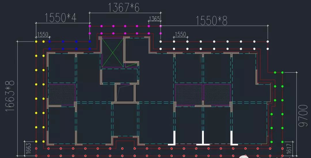
The layout is as follows: Step 5: layout the vertical pole of the west elevation
.
If the length of the first section of the facade is 9700mm, then according to the above calculation method, the preliminary calculation is divided into several spans: 9700mm ➗ 1500=6.47。 According to the principle of even number, take 6 spans nearby, and calculate according to 6 spans, then the vertical distance of the facade is 9700 ➗ 6=1617。 Therefore, the vertical distance of the scaffold is 1617mm
.
The layout diagram is shown below: the sixth step is to arrange the layout of other long facades
.
The principle is the same as above: even number! The seventh step is to typeset the relatively short facade
.
For short facades, such as those with less than 4 vertical distances, it is not necessary to abide by the principle of even number and divide them equally
.
For example, the west elevation in the Yellow cloud line below
.
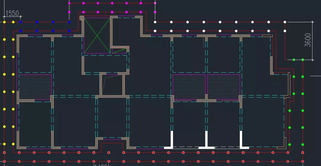
The eighth step is to calculate the number of poles
.
The length of the facade measured on CAD is 3600 mm
.
The principle of convenient typesetting is as follows: 3600 ➗ 3 = 1200mm, this part is directly replaced by zigzag brace (or half cross brace)
.
The layout diagram is as follows: the ninth step, the layout of other small elevation with the same principle
.
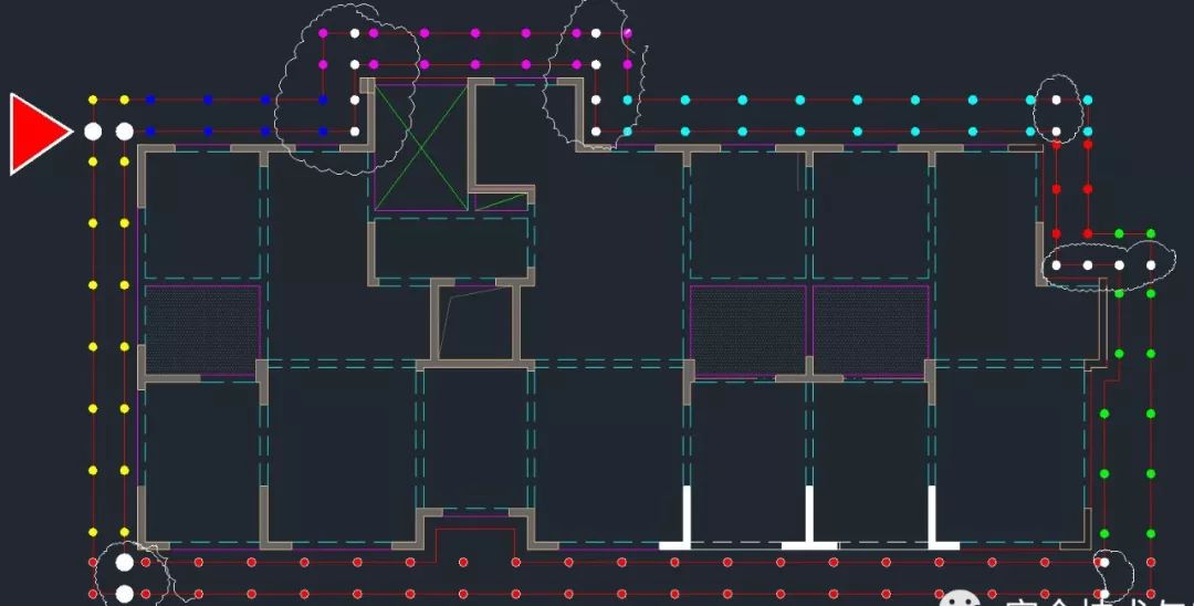
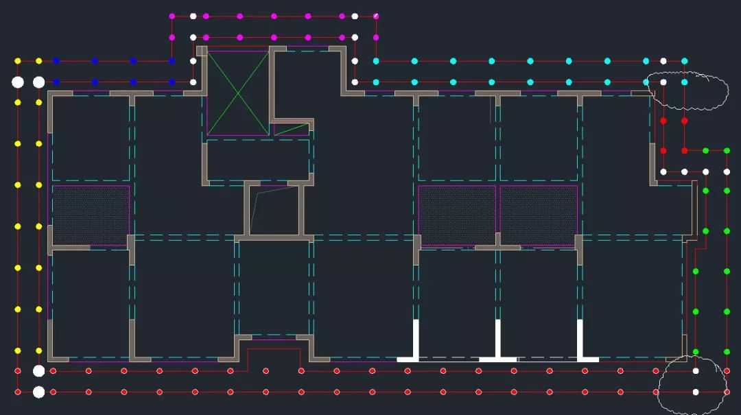
The tenth step, the outer frame corner part carries on the “well shaped frame” processing
.
That is to say, there must be a pole at the corner
.
Compared with the above figure and the following figure, the added vertical pole (the white dot in the figure) is as follows: step 11, simplify the special angle bracket
.
That is to say, one of the two adjacent poles can be simply removed (in order to ensure the grillage, the corner pole is generally reserved)
.
Compare the position of the pole in the cloud line of the figure below with the corresponding position of the figure above to see the reduced position of the pole
.
The twelfth step is to supplement and optimize the vertical pole for the concave position (the arrangement of vertical poles in the cloud line in the figure below is different from that in the figure above)
.
The fourteenth step is the completion of typesetting
.
If special nodes are encountered, such as elevator landing platform, cantilever unloading platform and other scaffold disconnection parts, the external frames on both sides of the disconnection shall be arranged according to the above method
.
The five principles of scaffold erection, if scaffold erection is difficult, can be summarized in the following two aspects: 1
.
Professional quality of scaffold erection personnel, which is mainly reflected in the erection standards and proficiency
.
2
.
The second point is that the management personnel should understand some professional technology and special nodes
.
Practice has proved that Overhanging Scaffold, first carrying out vertical pole typesetting, and then according to the vertical pole typesetting position, optimizing the treatment of I-beam typesetting, will be better than that It’s easier
.
According to the summary of practice, the layout of the external shelf is summarized into the following five principles: 1
.
The scissors are in the middle: the scissors are crossed on the vertical pole (see 130-2011 for requirements)
.
Article 6.6.2, Article 3 of jgj130-2011 stipulates: in other words, the cross bracing is either crossed on the small cross bar or on the vertical bar
.
In contrast, the crossing on the pole is beautiful, convenient and safe
.
2
.
Independent erection: the cross bar of material platform and elevator is independent, without or without cross bracing
.
The purpose of this setting is to make it convenient to install the material platform and set up the landing platform in the future, and save the waste of dismantling the cross bar or even cutting the steel pipe in the later stage
.
Of course, this design also needs to be optimized in advance
.
For example, the traditional material platform should be improved and optimized in advance: before optimization, the material platform (lower) should be optimized, and after optimization, the material platform (upper) should have 3 even numbers first: for a wider facade, the space between vertical poles should be equidistant (the span can be about 1500), divided into even numbers, and the longitudinal distance should be the same on each facade
.
The longitudinal distance on different elevations can be fine tuned, mainly for It is considered that the number of longitudinal spans of the vertical pole should be even
.
The actual erection effect is beautiful
.
4 scissors with span: the number of spans of the scissors is the same, generally the same as 4 spans, to ensure that the top of the scissors is flush
.
That is to say, the number of cross braces on a face is either an integer or half (that is, half of the cross braces are allowed to exist) 5 corner over the pole: the position of the second vertical pole from the corner is measured from the vertical pole at the corner, regardless of the vertical pole in the corner
.
The red and white poles in the picture belong to the inner and outer poles in the direction perpendicular to the screen, while the Yellow pole is the one facing us
.
Question: if the longitudinal distance of each elevation is not consistent, will there be a big difference in the angle of cross bracing, and the elevation is not beautiful? Answer: practice has proved that the vertical distance difference is about 10 cm, the effect of the erection is difficult to see, and the basic facade has no impact
.
Warm reminder official account: safety information sharing, industry information interpretation, long line code attention, we welcome you to work for security cause! Just for your daily improvement.
.