Bracket and steel pipe column Bailey beam cast-in-place simply supported box girder are widely used in bridge engineering, so what is their basic structure like? What kind of safety accidents will happen if the project fails? ” 1: Steel pipe column Bailey beam erection structure 1
. 
Cast in place Bailey support is composed of steel pipe column, sand box, distribution beam, Bailey beam, bottom formwork, side formwork and support from bottom to top
. 
2
. 
Steel pipe column a, steel pipe column generally adopts diameter Φ 1000mm spiral steel pipe can transfer the dead weight of beam structure, support load and construction load to the foundation
. 
In order to ensure the stability of steel pipe columns, the adjacent steel pipe columns are connected with 〔 10 〕 channel steel
. 
The top of the column is supported by the distribution beam, and the lower part is supported on the pile cap or foundation
. 
b
. 
The bottom end of steel pipe column is welded with 110 mm thick steel pipe × 110cm steel plate with four corners fixed by expansion bolts
. 
In order to strengthen the stability of the steel pipe column, a “well” shaped support is set in the end of the steel pipe column
. 
The top of steel pipe column and the middle of span are fixed on the pier body with 〔 20 〕 channel steel
. 
3
. 
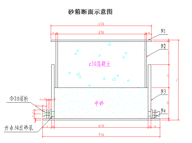
In order to facilitate the removal of bottom formwork, side formwork and Bailey beam, a sand box with adjustable height of 0.5m is installed between the top of steel column and I-beam
. 
4
. 
The distribution beam plays the role of distributing the structural load, support load and construction load to the steel pipe column
. 
5
. 
A single Bailey plate is generally 3M long and 1.5m high
. 
The Bailey plates are connected by pins, and the Bailey beams are connected by flower windows to strengthen their torsion resistance
. 
The Bailey beams are connected with flower windows to enhance their torsion resistance
. 
2、 Basic structure of full support construction 1
. 
Support structure
. 
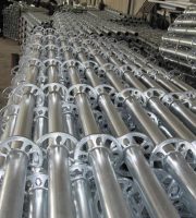
XX high-speed railway basically adopts bowl buckle type support
. 
The bowl buckle node is composed of upper bowl buckle, lower bowl buckle, vertical bar, cross bar joint and upper bowl buckle limit pin
. 
The bowl buckle joint of vertical pole is set according to 0.6m modulus, and the sleeve and connecting pin hole are used for the extension of vertical pole
. 
The specification of steel pipe for bowl buckle frame is Φ forty-eight × 5 mm, and the wall thickness of steel pipe shall not be less than 3.5-0.025 mm
. 
The upper bowl buckle, adjustable base and adjustable supporting nut shall be made of malleable cast iron or cast steel, while the lower bowl buckle, cross bar joint and diagonal bar joint shall be made of carbon cast steel
. 
2
. 
Support foundation treatment ( According to the calculated bearing capacity) When the foundation is excavated to the original soil, the bearing capacity of the foundation shall be at least 180kpa
. 
The foundation shall be replaced with notoginseng lime soil not less than 0.6m, and the foundation shall be tamped with air tamping
. 
The bearing capacity of the replacement part shall be at least 250kPa
. 
Special attention shall be paid to the replacement of mud pit and foundation pit of bearing platform; 0.2m C25 concrete is poured on the top surface
. 
3
. 
Support erection 4
. 
Support preloading in order to ensure the quality of the box girder concrete structure, the steel pipe scaffold must be preloaded after the support erection is completed and the bottom formwork is laid, so as to eliminate the inelastic deformation of the support, support square timber and formwork and the influence of the compression settlement of the foundation, and obtain the actual value of the elastic deformation of the support and foundation, It can be used as a reference for setting the pre arch value of beam formwork
. 
The preloading method is based on the weight distribution of the box girder concrete
. 
The preloading blocks or sandbags are stacked on the erected supports
. 
The preloading load coefficient is 1.3 times of the beam span load
. 
The preloading time depends on the ground settlement of the supports
. 
The supports are unloaded after 48 hours of stable settlement
. 
The loading process is divided into four stages: 0-30 ‰ – 60 ‰ – 100 ‰ – 130 ‰
. 
5
. 
The unloading of the support is still carried out by stages, and the unloading is carried out in the reverse order of loading
. 
First unload 30% of the overload preloading, then unload the weight of the top plate, then unload the weight of the web, and finally unload the weight of the bottom plate
. 
Every time the first level load is removed, all measuring points are measured once, and detailed records are made, and the deflection is compared with that of loading during data analysis
. 
6
. 
There are five sections in the longitudinal direction of the bridge: 2m at the end of the span, 1 / 4 span, 1 / 2 span, 3 / 4 span and 2m at the end of the span
. 
The sections are I, II, III, IV and V from small mileage to large mileage; Each section has seven points, which are flange bottom, web top, both sides of bottom plate, and the corresponding lower distribution beam position in the middle of bottom plate
. 
Along the forward direction of the line, from left to right, they are points 1 to 7
. 
A total of 35 points
. 
The layout of specific points is shown in the following figure: 3
. 
Formwork support is a field of heavy casualties
. 
When all kinds of construction support collapse in the bearing and use, most of them will cause quite serious consequences
.
Especially the collapse accident of the support in the pouring, often cause heavy casualties, huge economic losses and adverse social impact
.
Therefore, no matter from which aspect, we must attach great importance to the research on the collapse of formwork support, and take strong technical support and management measures to prevent and eliminate the collapse of formwork support( 1) The collapse of formwork support has always occupied a high proportion in major engineering construction accidents
.
According to incomplete statistics of relevant data: from 1992 to 1995 In the first half of the year, 83 kinds of collapse accidents occurred in China 16 cases (19.3%) collapsed; In 1992, a major accident occurred in China, in which more than 3 people died, 59 people died and 20 people were seriously injured due to floor collapse, accounting for 38% and 59% of the total respectively; The collapse of formwork support has always occupied a high proportion in major engineering construction accidents
.
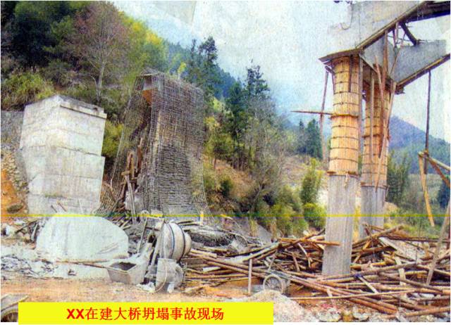
( 2) The typical collapse accident of formwork support in recent years occurred on September 5, 2005
.
XX project, the project did not carry out the expert group argumentation on the construction scheme according to the regulations, the support scheme was set up without approval (when the second draft was submitted, the support had been set up), and there were some problems, such as the extension length of the vertical pole was 1.4 ~ 1.7m, the cross bar was missing, the fastener tightening degree was generally unqualified, the diameter of the adjustable bracket screw rod was too small, the floor sweeping rod was too high, and the bowl buckle frame was mixed (no upper bowl buckle, no upper bowl buckle, no upper bowl buckle) There are many problems, such as the floating of the cross bar and the random erection of the cross bar
.
Although the supervisor did not sign on the draft of the scheme for approval, there was no document to stop the erection and pouring of concrete
.
When the pouring of the floor was nearly completed, a concave collapse suddenly occurred from the southwest part of the middle of the floor, resulting in 8 deaths and 21 serious injuries
.
On October 20, 2009, the side span support collapse accident of continuous beam of XX super large bridge on XX high-speed railway occurred because the welding point of the lower bowl buckle and the upper column with serious welding quality problems was broken, resulting in the instability of a single column
.
The sudden instability of a single column led to the destruction of the cross beam, and the contact instability of the adjacent columns was caused by the fall of the preloading soil bag, resulting in the vertical collapse of the support
.
It is no problem that the support scheme is checked layer by layer, but the inspection and acceptance of the support on site are not in place, resulting in the accident( 3) The basic characteristics of multiple accidents are as follows: 1) the environment, conditions, factors and a large number of hidden dangers that cause accidents exist for a long time in corresponding fields; 2) Similar accidents happen constantly; 3) Accidents of the same or similar causes occur repeatedly
.
4、 From a technical point of view, the collapse of formwork support of scaffold structure is caused by the following two situations, or both: first, the actual load on the scaffold or its members and joints exceeds its actual bearing capacity, especially the stable bearing capacity; second, the actual load on the scaffold or its members and joints exceeds its actual bearing capacity; The second is that the frame body is subject to the undesired load action (side force, pulling, torsion, impact, etc.), or the frame body is subject to the undesired setting and working state change (inclination, sliding, uneven settlement, etc.), which leads to the failure of the original design stress state
.
The direct cause of formwork support collapse The first aspect is that the support has no bearing capacity to ensure safety due to design and construction defects
.
Second, because of design or construction reasons, the bearing capacity of the support is not very rich.
.

