It shall be set in full length to avoid formwork expansion and slurry leakage without proper reinforcement, so as to ensure the visual effect of the internal corners of the top plate and the wall.

8.
3.
The square steel shall be used together with the square steel, and the wood square shall be adjusted according to the size of the square steel.

6.

9.
Wood shall not be lower than second-class wood, and brittle, seriously twisted and easily deformed after moisture shall not be used.
The edge of the top plate shall be leveled and reinforced.
3.


2.
Multilayer board quality standard wall, column and beam formwork shall adopt not less than 14mm thick coated board (actual thickness) except for special requirements; The actual thickness of floor formwork shall not be less than 12mm thick multi-layer coated plate.
Derived from| Zhongtian construction sorting| Douding construction I.

Install each piece of column formwork pre assembled in place: now put the two adjacent pieces in place, bind them with iron wire and main reinforcement for temporary fixation, and then install the other two pieces of formwork..
The distance between upright poles of formwork erection shall be controlled within 1200mm, the distance between upright poles and the wall shall not be more than 300mm, and the height of upright poles shall be about 250-400mm lower than the clear height of the floor; Three horizontal pipes shall be set on the standard floor, the free end of the upper end of the steel pipe shall not exceed 500mm, the adjustable U-shaped jacking thread shall not exceed 200mm, and the diameter shall not be less than 36mm.
The falling plate formwork of indoor floor 1) the tool type hanging formwork is made of section steel, which shall be cleaned and brushed with release agent before each use.

7.


The formwork shall be installed after the overall assembly on site (the assembled small plate shall be placed in the middle of the wall), and the formwork shall be jointed vertically.

2.
Snapping and cutting the wall edge, and press polishing and leveling within 200 of the wall edge.
During the inspection and acceptance of floor formwork, the repair of floor deviation requires relevant woodworking operators to adjust synchronously at the bottom of the slab.
4) Install split screw at 100mm from the wall to the plug plate.

The joint position of the formwork shall be set reasonably, and the wooden square shall be set at the joint outside the formwork to connect the formwork on both sides.
The external corner of the wall is reinforced with split bolts.
4.
The lower opening of the wall is tightly pressed with the top panel by large head wood chips.
The main keel shall be installed with 80 * 80mm square steel or 100 * 100mm square timber.
Before column formwork installation, a control line 500 away from the edge must be snapped to review the positioning accuracy of column formwork.
The beam with web height less than 450 shall be reinforced with U-shaped square timber hoops, and the spacing shall not be greater than 600.
2) The side of the plug plate shall be planed to ensure straightness and shall be installed by hard splicing.
The beam with web height greater than 450 shall be equipped with split pull screws (one pair of wire drawing rods shall be added every 300, and the vertical rod support shall be added at the beam bottom) to prevent formwork expansion.

The gap between formworks shall not be greater than 1mm, and putty mixed with varnish and putty powder can be used to fill the plate gap locally.

The wall end shall be firmly clamped with double steel pipes.

Formwork bottom elevation and wall perpendicularity – Inspection and acceptance control by management personnel 6.
2.


After the formwork is installed, the elevation of the upper surface of the bottom formwork shall be ± 3mm, and the allowable deviation of flatness shall not be greater than 2mm.
Mobilization inspection: boiled in boiling water for 24 hours without deformation, peeling and glue opening, and then exposed to the sun for 4 hours without peeling.
Sponge strips shall be pasted on the concrete wall 2-3mm below the elevation of the top plate formwork to prevent slurry leakage.
Screw holes shall be drilled in the side beam formwork, cement lining strips shall be placed in the beam to control the beam section size, screw in, iron nails shall be nailed at the gasket to fix the screw, and it is recommended to change the split bolt on the outer side of the beam into a three connection screw rod, which can save steel.
3、 Key process control of beam formwork erection 1.
The edge of the top plate shall not be disconnected.
The wood board is cut with a precision panel saw to ensure the flatness of the cutting section.
The top plate formwork shall be provided with edge wood.
After the wood pressure planing is completed, it shall not be less than 35 * 85mm.
5.
The thickness of the multi-layer plates is 50mm, and the outer opening is flush with the top wood square.
6.


3.
Both sides of the beam can be fixed with fasteners in the form of square timber to ensure the beam size The position shall be accurate, and the bottom elevation of beam formwork shall be checked through the structural 50 line on the reinforcement.

Before the formwork erection of flat plate formwork, draw the formwork matching drawing of standard layer flat plate, number the flat plates of different sizes, and then set out each flat plate (configure the detailed formwork matching drawing of single block) for centralized formwork matching.

The width and straightness of the lath shall be trimmed by electric planer to the nearest millimeter.
All shear walls shall be provided with steel pipe top bearing and steel wire rope stay cable to ensure wall perpendicularity to prevent wall displacement during concrete pouring.
Control of key process of roof formwork erection 1.
8.
3.
The surplus space is tightly packed with multi-layer plates.
2.
4.
One side of the beam in the direction of vertical back edge wood beside the shear wall is exposed for 15mm, so that the wood can support the shear wall side formwork and beam side formwork at the same time.

4、 Key process control of shear wall formwork erection 1.
For the 200 width around the column, it shall be leveled and calendered when the top slab concrete is finished.
2.

Judgment method of multilayer board quality 5.

Press planing shall be carried out for the mobilized timber (it is recommended that the supplier enter the site after press planing), so as to ensure that the size of the treated timber is accurate and unified.
quality control of raw materials 1.
The bottom bolt is consistent with the bolt on the outer side of the top plate.

Support formwork of shear wall plug plate 1) the positioning reinforcement of wall and plug formwork shall be welded at the plug position of shear wall.

3) The plug plate is installed by clamping the wall formwork inside, and the external back ridge square wood and steel pipe reinforcement.
The cantilever length at the end shall not exceed 250mm, and the distance from the wall shall be controlled within 150mm.
After formwork removal, nail wood strips and other measures shall be taken to protect the external corners.
Roof side formwork: it is processed with 15mm thick multi-layer plate and 50 * 100mm wood cube.

If the formwork is lost, double-sided tape shall be used to prevent slurry leakage.
It is convenient to ensure the accuracy of the position of wall formwork erection.

5、 Key process control of frame column formwork erection 1.
The distance between the wooden keel or section steel layout and the wall shall be controlled within 150mm, and the cantilever length shall be controlled within 250mm.
The joint gap between formworks shall not be greater than 1mm, and the height difference between two formworks at the joint shall not be greater than 2mm.
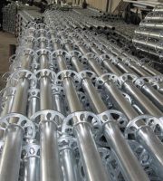
Formwork erection adopts the form of coil buckle frame or bowl buckle frame + adjustable U-supporting roof.

2) When pouring concrete, strictly control the floor elevation and the formwork removal time.
The layout of wooden keel or section steel of floor formwork shall be uniform, and the clear space distance shall not exceed 200mm (within 150mm of plate thickness).
The corner assembly is connected by pins, and the horizontal elevation and axis position are controlled by welding positioning cards.
It is processed intensively according to the outer lines of the roof and numbered for turnover at the corresponding position of each layer of processing and forming outer wall.
The bottom of each steel pipe shall be provided with wooden skids with a length of not less than 250mm.

After the installation of the top plate formwork, first use the pull wire to detect the formwork range (if possible, use the laser leveling instrument to measure), and also use the aluminum alloy ruler to detect the flatness of the plate surface.

Before concrete pouring, the wooden formwork shall be watered and wetted, but there shall be no ponding in the formwork.
4.
The distance between the lower opening of the split bolt of the wall body and the ground shall not be greater than 200mm, the distance between the upper opening and the top plate shall be less than 250mm, the horizontal spacing shall not be greater than 500mm, and the distance between the split bolt at the corner and the internal corner shall not be greater than 150mm.

When installing the upper wall (column) formwork of formwork and small steel formwork, extend the formwork and vertical bar (square timber) more than 200mm to the poured concrete wall (column), press down the transverse keel, and tighten the vertical bar of the formwork with the original screw or embedded screw of the poured concrete.

5.

In case of L-shaped and T-shaped walls, the horizontal pull rod and opposite wire drawing rod shall be set in full length, and the end section shall also be fixed with pull rod.


The contact surface between formwork and concrete shall be cleaned.
Vertical and horizontal two-way sweeping rods shall be set at the bottom of the column 200mm above the ground.
It is recommended that the floor support model steel be used together with the square timber: the square timber shall be replaced by the square steel pipe, and the square timber shall be used only at the joint of the structural plate to ensure the flatness of the formwork and reduce the use of timber, but the uniformity of the dimensions of the square timber and the square steel pipe must be ensured.

The construction control lines of shear wall include door opening sideline, wall sideline, wall large corner broken line and 50 control lines of the above sidelines.
Auxiliary materials and tools for wood formwork construction II.
7.


