See the attached drawings for the winding specifications.
After the pull wire is tightened, the pole tip shall be inclined to the outer corner by about one pole tip; the pole body of the terminal pole shall be inclined to the pull wire side by 10 ~ 20cm.
The optical cable line is crossing the power When crossing the line, it is necessary to contact the local electrician and take suspension of power supply or other safety measures before crossing the cable, so as to ensure the personal safety of the power supply line and personnel; when crossing the highway, warning signs must be set at corresponding positions to ensure the safety of construction personnel.
II.
4.
Optical cable grounding in the machine room: after the optical cable enters the machine room, the optical cable reinforcing core must be strengthened It must be connected to the lightning protection ground wire row of ODF frame, and the lightning protection ground must be connected to the outdoor ground wire row with 16mm2 power line.
Steel strand or 4.0 iron wire is used according to the actual situation.
Optical cable laying 6.
20m is reserved at each end of the incoming and outgoing office, and 8-10m is reserved for each pole at the front and rear of the joint box at the optical cable joint.
3、 1.
In some sections, in case of topographic constraints, such as river crossing, and long span, it shall be treated as overhead flying line.
The square stay wire shall be directly grounded with ground rod, and all overhead lines shall be grounded at least every 1km.
It is specially required that the terminal pole, lead-in pole and the first five electric poles of the bureau must be equipped with directly buried lightning protection grounding wire; 2.
Construction precautions: (1) the pole can be erected only after the hole depth is qualified.
The distance height ratio of stay wire should be 1, not less than 0.75; the distance height ratio of stay rod should be 0.6, not less than 0.5.
Generally, there are eight steps: 1.
The termination of suspension cable shall be wrapped separately, and the connection of suspension cable shall be “socket connection” Method: the two ends of the socket connection shall be wrapped separately.
One wind proof stay wire (herringbone pull) shall be set for every 16 gears of the straight pole; one ice proof stay wire (four-way pull) shall be set for every 32 poles [the downwind stay wire pulled by the Quartet is set at 10-15cm above the suspension line and used as an auxiliary line, and the side stay wire is set at 25-30cm below the suspension line.
Optical cable connection 7.
The treatment method will be described in detail in the later part of laying hanging line.
Pole label The design paragraph shall be prepared as an independent unit.
3.
When the first suspension line is erected on the pole road, the suspension line shall be set in the forward direction (facing the B end) The suspension cable shall be laid below the power line as far as possible.
3.
The optical cable hook adopts 25mm plastic support hook with an interval of 50cm.
The installation position of suspension cable splint shall be no less than 50cm from the top of the pole, and no less than 25cm in special cases.
II.
Crossing two high-voltage power lines The pole, stay wire and suspension wire at the end must be grounded; the overhead line parallel to the power line shall be grounded every 200m; 4.
Laying of suspension wire 4.
6.
2.
4、 Setting requirements for lightning protection wire and ground wire lightning protection grounding wire: 1.
If the overhead suspension line is found to have jumping strands, loose stranding and other disabled parts that are detrimental to the mechanical strength of the suspension line, it shall be cut off and then connected.
Pull wire lightning protection grounding wire shall be installed for the end of discharge, corner pole, crossing pole, bifurcation pole, slope top pole and electric pole more than 12M, and the suspension wire shall also be grounded at the same time, and the lightning wire shall be 10cm higher than the pole top; 3.
The pole size face shall face the highway, black words on white background, Arabic numerals and other requirements.
Rod distance The basic pole spacing is 50m, which can be adjusted to 60m according to the terrain of mountainous area.
1、 Pole 1.
For overhead optical cable, one place is reserved for every 10 poles, with a reserved amount of 10m and a reserved diameter of 60cm.
(5) When the line crosses the 10kV power line, lightning wires shall be installed on the poles on both sides.
The terminal is fixed with the base station machine room by terminal climbing, and the optical cable is introduced into the machine room.
optical cable laying 1.
4.
7m basic pole hole depth The surface is made of stone up to 0.9m and other soil up to 1.2m.
4.
Pole erection 2.
When it exceeds, the auxiliary device for pitch angle shall be installed; when the corner depth is greater than 5m, the auxiliary device for inner or outer corner shall be required.
Pole type The basic pole is 7m high and the tip diameter is 150mm.
In case of special sections, crossing obstacles or roads and railways, 8m and 9m pole heights can be selected according to the actual terrain.
Let’s understand these eight steps in detail.
(4) the soil return shall be compacted in layers, and the soil return of the solidified pavement in the urban area shall be flush with the pavement; the soil in the suburbs shall be 10-15cm higher than the pavement.
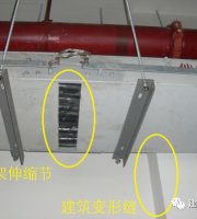
A “U” is made for every 3 poles Type expansion bend shall be reserved.
3.
7.
The lowest word should be 2.5m above the ground.
The laid optical cable must use the optical cable that has passed the inspection of a single disc of optical cable.
1.
Before mounting the pole, check the firmness of the foot buckle, safety belt and the surrounding environment on the pole to avoid safety accidents.
Construction requirements: 1.
2.
The optical cable suspension cable shall be fixed on the pole with suspension cable hoop and three eye single slot splint.
The sag of the suspension line shall meet the design requirements and should be equidistant from the ground.
The program of stay wire shall meet the design requirements.
Special sections (such as crossing rivers, bridges, etc.) shall be reserved according to the actual situation..
5.
6.
The position of the suspension line clamp shall meet the space and spacing between the hanging optical cable and other buildings at the top, bottom, left and right.
In some sections, if there are topographic restrictions, such as crossing a river, and the span is long, it shall be treated as an overhead flying line When the pole spacing is ≤ 120m, 7 / 2.2 steel strand shall be used; when the pole spacing is 121m-300m, long pole stop treatment (top stay wire or three-way stay wire shall be set and auxiliary wire shall be used), 7 / 2.6 steel strand shall be used, and 7 / 3.0 steel strand shall be used for stay wire; when the pole spacing is 301m-500m, flying wire treatment (main and auxiliary suspension wire shall be used) , 7 / 2.2 steel strand is used for the main suspension line, 7 / 2.6 steel strand is used for the auxiliary suspension line, square stay wire is used for the crossing pole, three-way stay wire is set for the adjacent pole, the crossing pole is used as the auxiliary line (main and auxiliary suspension line), the auxiliary suspension line is terminated at the adjacent pole, and 7 / 3.0 steel strand is used for the stay wire; when the pole distance is > 500m, it is treated as flying wire (main and auxiliary suspension line) The crossing pole is erected with H pole, the main suspension line is 7 / 2.6 steel strand, the auxiliary suspension line is 7 / 3.0 steel strand, the crossing pole is made of six stay wires, the adjacent pole is set with three-way stay wires, the crossing pole is made of auxiliary line (main and auxiliary suspension wires), the auxiliary suspension wire is terminated at the adjacent pole, and the stay wire is made of 7 / 3.0 steel strand.
The soft suspension cable is used to lead into the base station, that is, the suspension cable is not tightened.
See the code for acceptance of local network communication line engineering for details 5.
Technical specification requirements: 1.
If the angle depth is greater than 15m, two top stay wires shall be installed on the corner pole.
(2) The deviation between the center vertical line of the electric pole (middle pole) on the straight line and the center line of the route shall be less than 5cm, and the electric pole itself shall be vertical up and down; the root of the angle pole shall be moved inward by half (10 ~ 15cm).
V.
(3) The rod root chassis, chuck and other root fixing devices shall meet the design requirements.
5.
Installation of stay wire 3.
Angle rod The stay wire shall be on the extension line of the bisector of the inner corner; the terminal stay wire shall be on the center line of the line.
The anchor and stay wire can be buried only after the depth of ground anchor is checked to be qualified.
The gradient change of the suspension line shall not exceed 5% of the pole distance.
Lightning protection wire and ground wire 5.
50 ~ 80cm on both sides of the pole shall be bound with a single strand leather wire.
5.
The installation of stay wire.
It cannot be buried in the rock zone When the ground anchor block is used, a hole can be drilled on the rock (non wind fossil), 1 / 2 of the hole can be filled with 1:3 cement mortar, the ground anchor with threaded steel handle (at least 26mm in diameter and 0.5m in length) can be driven, sealed and leveled, and the steel handle is 90 ° with the direction of the stay wire.
Project acceptance.
2.
The actual excavated length of stay wire ground anchor is 30 ~ 60mm.
3.
Method of stay wire: the upper handle of the stay wire in this phase of the project adopts the splint plus another winding method, and the middle handle adopts another winding method.
The lowest point of the expansion bend shall be 25-30cm away from the suspension line.
2.
Each stay wire shall be grounded with the help of stay wire, and lightning protection wire shall be set here.
Optical cable termination and testing 9.
3.
The place where the optical cable contacts the pole shall be protected with a corrugated pipe with a length of 20cm.
2.
8.
The stay wire close to the high-voltage power facilities shall be equipped with grounding device according to the design regulations.


