3) ambient temperature and test medium temperature a) liquid temperature during liquid pressure test.
At least 2 pressure gauges with accurate calibration shall be set for the pipeline system, and the full scale value of the pressure gauge shall be 1.5 ~ 2 times of the measured maximum pressure.
2) the pressure test flow chart shall include the following contents: a) pipe No.; (b) medium flow direction; (c) design pressure and design temperature; Test pressure Test temperature ^ d) air discharge point in the system ^ E) temporary reinforcement position for pressure test (if the expansion joint needs to be equipped with temporary beam release device) F) location of temporary blind plate {g) test medium inlet} h) test medium discharge} I) location of pressure gauge 3.1.4} setting of temporary pipeline and blind plate} 1) pressure test blind plate: temporary blind plates shall be added for equipment, instruments, safety valves, bursting discs and operating pipelines that cannot participate in system pressure test due to different test pressures or other reasons.
Thickness calculation of pressure test blind plate: according to ANSI / asmeb31 32) soft copper gasket can be selected as the temporary gasket of high-pressure pipeline.
Vent valve is set at the high point and discharge valve is set at the low point of the system.
3.
When not specified in the design document, the test shall comply with the following provisions: 1) the test medium # liquid pressure test shall be carried out with clean water.
1) manufacturer’s quality certificate of pipe components and welding materials 2) calibration inspection or test records of pipe components and welding materials 3) pipe bend processing records, pipe end thread and sealing surface processing records 4) pipeline system concealed works records 5) pipeline welding work records and welder layout Radiographic testing layout , 6) NDT report , 7) welding joint heat treatment record and hardness test report , 8) electrostatic grounding test record , 9) design change and material substitution document..
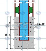
The temporary pipeline connection is shown in figure 3.1.4.
3.2 confirmation of pressure test conditions 3.2.1 data review the construction unit shall sort out the following data according to the approved pressure test scheme and submit it to the project quality supervision station, which shall organize the owner / Supervisor and relevant departments for review and confirmation.
B) the test pressure of pipeline with design temperature higher than 200 ℃ shall be calculated according to the following formula: Pt – test pressure (MPA) k – coefficient, and 1.5 for liquid pressure test; P0 — design pressure (MPA)[ δ] 1 — allowable stress of material at test temperature (MPA)[ δ] 2 — allowable stress of material at design temperature (MPA) C) during liquid pressure test, it shall not exceed 90% of material yield point at test temperature.
2.
Formulation of pressure test scheme 3.1.1.
When required by the production process, other liquids can be used.
3.1.2 determination of pressure test parameters when specified in the design document, it shall be carried out in accordance with the provisions of the design document.
3.1.3 ^ relevant requirements for drawing the pressure test flow chart ^ 1) in principle, the pressure test flow chart adopts the method of marking on the PID diagram (that is, mark the pipe number of pressure test on the PID diagram with a colored pen); Or arrange and draw the pressure test flow chart by hand or computer according to the PID diagram; Under special circumstances, the construction single line diagram can be used as the pressure test flow chart.
Material of pressure test blind plate: carbon steel is generally selected.
2.3 main equipment and machines: high pressure plunger pump, electric welding machine, cutting grinder, polishing grinder, oxygen gauge, pressure gauge, electric hoist, hydraulic wrench, electric wrench, etc.
Materials for measures: high pressure thick wall seamless steel pipe, high pressure pipe fittings, high pressure rubber hose, oxygen belt, section steel, pressure gauge joint, steel valve, screw head, blind plate, gasket, etc.
During the water test of austenitic stainless steel pipeline, the chloride ion content in the water shall not exceed 25mg / L.
Pressure test operation process 3.1.
2) test pressure a) the pressure of liquid pressure test is 1.5 times of the design pressure.
3.1.5 the pressure test scheme shall be prepared by the technical director of pressure test, reviewed by the quality assurance engineer of the project or engineering company, and approved by the technical director of the construction company.
The material selection of temporary pipeline and its components shall be based on the highest system pressure test pressure.
2.2.
Pressure test materials 2.1 consumable materials: selected according to pressure test requirements and site conditions: welding electrode, oxygen, acetylene gas, etc.
Application scope of general construction process 1 for pressure test of high pressure pipeline this process is applicable to the hydraulic test of industrial metal pipeline system with design pressure greater than or equal to 10MPa and less than 42MPa.
3) The temporary pipeline shall be high-pressure seamless steel pipe, and its pipes, fittings and valves shall be the same as the formal engineering materials, with product quality certificate; The welding process is the same as that of the formal pipeline.
The system division is based on the PID flow chart, pipeline list and single line diagram provided by the Design Institute, and the principle that the test medium and test pressure are the same constitutes the pipeline pressure test system.
When it is not specified in the design, the liquid temperature of non alloy steel and low alloy steel pipeline system shall not be lower than 5 ℃; For the piping system of alloy steel, the liquid temperature shall not be lower than 15 ℃ and shall be higher than the brittle transition temperature of corresponding metal materials.